


Section II Operating Instructions Teledyne API T802 Paramagnetic O
2
Analyzer Operation Manual
54
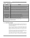
Table 3-10: Warning Messages
MESSAGE
MEANING
ANALOG CAL WARNING
The instrument’s A/D circuitry or one of its analog outputs is not calibrated.
BOX TEMP WARN
The temperature inside the chassis is outside the specified limits.
CANNOT DYN SPAN
3
Remote span calibration failed while the dynamic span feature was set to turned on
CANNOT DYN ZERO
4
Remote zero calibration failed while the dynamic zero feature was set to turned on
CO2 ALRM1 WARNING
1, 2
Concentration alarm 1 is enabled and the measured CO
2
level is ≥ the set point.
CO2 ALRM2 WARNING
1, 2
Concentration alarm 2 is enabled and the measured CO
2
level is ≥ the set point.
CO2 CELL TEMP WARN
1
CO
2
sensor cell temperature outside of warning limits.
CONFIG INITIALIZED
Configuration storage was reset to factory configuration or erased.
DATA INITIALIZED
DAS data storage was erased.
O2 ALRM1 WARNING
2
Concentration alarm 1 is enabled and the measured O
2
level is ≥ the set point.
O2 ALRM2 WARNING
2
Concentration alarm 2 is enabled and the measured O
2
level is ≥ the set point.
O2 CELL TEMP WARN
O
2
sensor cell temperature outside of warning limits.
REAR BOARD NOT DET
The CPU is unable to communicate with the motherboard.
RELAY BOARD WARN
The firmware is unable to communicate with the relay board.
SAMPLE FLOW WARN
The flow rate of the sample gas is outside the specified limits.
SAMPLE PRESS WARN
Sample gas pressure outside of
operational parameters.
SYSTEM RESET
5
The analyzer was rebooted or the CPU was reset.
1
Only enabled when the optional CO
2
Sensor is installed.
2
Alarm warnings only present when optional concentration alarm relay package is installed.
3
Clears the next time successful span calibration is performed.
4
Clears the next time successful zero calibration is performed.
5
Does not clear after power up.
3.4.2. FUNCTIONAL CHECKS
After the analyzer’s components have warmed up for at least 60 minutes, verify
that the software properly supports any hardware options that were installed. For
information on navigating through the analyzer’s software menus, see the menu
trees described in Appendix A.1.
Check to make sure that the analyzer is functioning within allowable operating
parameters. Appendix C includes a list of test functions viewable from the
analyzer’s front panel as well as their expected values. These functions are also
useful tools for diagnosing performance problems with your analyzer (see Section
11.1.2).
The enclosed Final Test and Validation Data Sheet (PN 068350000) lists these
values before the instrument left the factory.
Remember until the unit has
completed its warm up these parameters may not have stabilized.
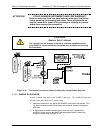
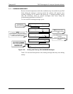
If your local area network (LAN) is running a dynamic host configuration
protocol (DHCP) software package, the Ethernet will automatically configure its
interface with your LAN. However, it is a good idea to check these settings to
07275B DCN6418