


Principles of Operation Teledyne API T802 Paramagnetic O
2
Analyzer Operation Manual
232
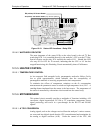
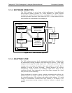
D6
(
Y
ellow
)
O
2
Sensor Heater
D5 (Yellow) –CO
2
Sensor Heater (only with CO
2
option)
D1 (RED)
Watchdog Indicator
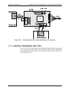
Figure 12-12: Status LED Locations – Relay PCA
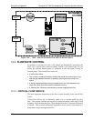
12.5.4.2. WATCHDOG CIRCUITRY
The most important of the status LEDs on the relay board is the red I
2
C Bus
watch-dog LED. It is controlled directly by the analyzer’s CPU over the I
2
C Bus.
Special circuitry on the relay PCA watches the status of D1. Should this LED
ever stay ON or OFF for 30 seconds, indicating that the CPU or I
2
C bus has
stopped functioning, this Watchdog Circuit automatically shuts off all heaters.
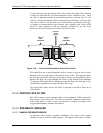
12.5.5. HEATER CONTROL
12.5.5.1. TEMPERATURE CONTROL
At low magnetic field strengths levels, paramagnetic molecules follow Curie's
law to good approximation, which indicates that the susceptibility of
paramagnetic materials is inversely proportional to their temperature.
To minimize the effects of temperature variations on the O
2
concentration
measurement the parametric sensor is raised to a high temperature level, 50C. A
cartridge heater implanted into the sensor is the heat source. The temperature of
the sensor is measured by a thermistor also inserted into the sensor body.
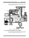
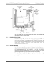
12.5.6. MOTHERBOARD
This printed circuit assembly provides a multitude of functions including, A/D
conversion, digital input/output, PC-104 to I
2
C translation, temperature sensor
signal processing, and serves as a pass-through for the RS-232 and RS-485
signals.
12.5.6.1. A TO D CONVERSION
Analog signals, such as the voltages received from the analyzer’s various sensors,
are converted into digital signals that the CPU can understand and manipulate by
the analog to digital converter (A/D). Under the control of the CPU, this
07275B DCN6418