Teledyne API T802 Paramagnetic O
2
Analyzer Operation Manual Troubleshooting and Service
207
11.3.2.5. ACTUAL FLOW DOES NOT MATCH DISPLAYED FLOW
If the actual flow measured does not match the displayed flow, but is within the
limits of 100-140 cm
3
/min, adjust the calibration of the flow measurement as
described in Section 10.3.4.
11.3.2.6. SAMPLE PU
MP
The sample pump should start immediately after the front panel power switch is
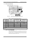
turned ON. With the SAMPLE inlet plugged the test function PRES should read
about 10”-Hg for a pump in good condition. Readings above 10” Hg indicate that
the pump needs rebuilding. If the test function SAMP FL is greater than 10
cm
3
/min there is a leak in the pneumatic lines.
11.4. CALIBRATION PROBLEMS
11.4.1. MISCALIBRATED
There are several symptoms that can be caused by the analyzer being
miscalibrated. Miscalibration is indicated by out-of-range Slopes and Offsets as
displayed through the test functions and is frequently caused by the following:
Bad span gas: This can cause a large error in the slope and a small error in
the offset. Delivered from the factory, the T802’s slope is within ±15% of
nominal. Bad span gas will cause the analyzer to be calibrated to the wrong
value. If in doubt have the span gas checked by and independent lab.
Contaminated zero gas: Excess H2O can cause a positive or negative offset
and will indirectly affect the slope.
Dilution calibrator not set up correctly or is malfunctioning: This will also
cause the slope, but not the zero, to be incorrect. Again the analyzer is being
calibrated to the wrong value.
Too many analyzers on the manifold: This can cause either a slope or offset
error because ambient gas with its pollutants will dilute the zero or span gas.
11.4.2. NON-REPEATABLE ZERO AND SPAN
As stated earlier, leaks both in the T802 and in the external system are a common
source of unstable and non-repeatable readings.
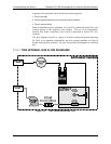
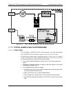
1. Check for leaks in the pneumatic systems as described in Section 10.3.3.
Don’t forget to consider pneumatic components in the gas delivery system
outside the T802 Such as:
A change in zero air source such as ambient air leaking into zero air line,
or;
A change in the span gas concentration due to zero air or ambient air
leaking into the span gas line.
2. Once the instrument passes a leak check, do a flow check (See Section
10.3.4) to make sure adequate sample is being delivered to the sensor
assembly.
3.
Confirm the sample p
ressure, wheel temperature, bench temperature, and
sample flow readings are correct and have steady readings.
07275B DCN6418


