


Principles of Operation Teledyne API T802 Paramagnetic O
2
Analyzer Operation Manual
224
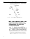
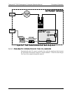
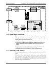
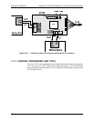
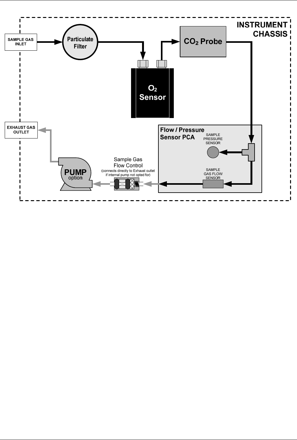
Figure 12-5: T802 – Internal Pneumatic Flow with CO
2
Sensor Option
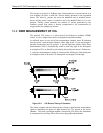
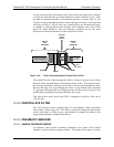
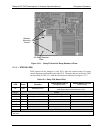
12.4. FLOW RATE CONTROL
To maintain a constant flow rate of the sample gas through the instrument, the
T802 uses a special flow control assembly located in the exhaust gas line just
before the optional internal pump or connected to the rear panel if using an
external pump. These assemblies consist of:
A critical flow orifice.
Two o-rings: Located just before and after the critical flow orifice, the o-rings
seal the gap between the walls of assembly housing and the critical flow
orifice.
A spring: Applies mechanical force needed to form the seal between the o-
rings, the critical flow orifice and the assembly housing.
A sintered filter: Removes particulates to prevent clogging the orifice
12.4.1. CRITICAL FLOW ORIFICE
The most important component of this flow control assembly is the critical flow
orifice.
Critical flow orifices are a remarkably simple way to regulate stable gas flow
rates. They operate without moving parts by taking advantage of the laws of fluid
dynamics. By restricting the flow of gas though the orifice, a pressure differential
is created. This pressure differential combined with the action of the analyzer’s
pump draws the gas through the orifice.
07275B DCN6418