


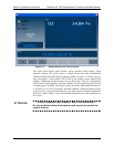
Section II Operating Instructions Teledyne API T802 Paramagnetic O
2
Analyzer Operation Manual
30
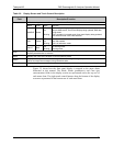
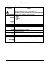
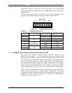
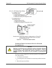
Table 3-3. Rear Panel Component Descriptions
Component Function
cooling fan
Pulls ambient air into chassis through side vents and exhausts through rear.
AC power
connector
Connector for three-prong cord to apply AC power to the analyzer.
CAUTION! The cord’s power specifications (specs) MUST comply with the power
specs on the analyzer’s rear panel Model number/Volt/Freq information label
Model/specs label
Identifies the analyzer model number and provides power specs
SAMPLE
Inlet connection to be used for any one of the following:
Sample gas
Span gas
Calibration gas
Zero air
EXHAUST
Connect an exhaust gas line of not more than 10 meters long here that leads outside
the shelter or immediate area surrounding the instrument.
SPAN 1
Not used.
SPAN2/VENT
Not used.
ZERO AIR
Not used.
RX TX
LEDs indicate receive (RX) and transmit (TX) activity on the when blinking.
COM 2
Serial communications port for RS-232 or RS-485.
RS-232
Serial communications port for RS-232 only.
DCE DTE
Switch to select either data terminal equipment or data communication equipment
during RS-232 communication.
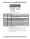
STATUS
For outputs to devices such as Programmable Logic Controllers (PLCs).
ANALOG OUT
For voltage or current loop outputs to a strip chart recorder and/or a data logger.
CONTROL IN
For remotely activating the zero and span calibration modes.
ALARM
Option for concentration alarms and system warnings.
ETHERNET
Connector for network or Internet remote communication, using Ethernet cable
ANALOG IN
Option for external voltage signals from other instrumentation and for logging these
signals
USB
Option for direct connection to personal computer, using USB com cable.
07275B DCN6418