


Teledyne API T802 Paramagnetic O
2
Analyzer Operation Manual
55
make sure that the DHCP has successfully downloaded the appropriate network
settings from your network server (see Section 6.3.1).
If your net
work is not running DHCP see your network administrator or
configure the Ethernet interface manually (see Section 6.3.2).
3.4.3. INITIAL CALIBRATION
To perform the following calibration you must have sources for zero air and span
gas available for input into the SAMPLE port on the back of the analyzer. See
Section 3.3.2 for instructions for connecting these gas sources.
The initial calibration should be carried out
using the same reporting range set up
as used during the analyzer’s factory calibration. This will allow you to compare
your calibration results to the factory calibration as listed on the Final Test and
Validation Data Sheet.
If both available DAS parameters for a specific gas type are being reported via
the instrument’s analog outputs e.g. CONC1 and CONC2 when the DUAL
range mode is activated, separate calibrations should be carried out for each
parameter.
Use the RNG1 button when calibrating for CONC1 (equivalent to LOW
RANGE).
Use the RNG2 button when calibrating for CONC2 (equivalent to HIGH
RANGE).
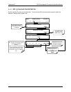
The calibration procedures assume:
that the zero point and span gases have been adjusted for known
interferents (Section 3.3.2.3)
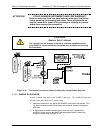
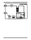
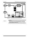
that the calibration gas will
be supplied through the SAMPLE gas inlet on
the back of the analyzer (see Figure 3-4), and;
that the pneu
matic setup matches that described in Section 3.3.2.4.
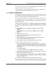
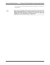
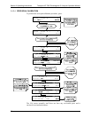
Perform the following outline of procedures for each sensor:
1. Verify the Reporting Range settings as presented in Section 3.4.3.1 While it
is possible to perform the following procedure with any range setting we
recommend that you perform this initial checkout using the following reporting
range settings:
Mode Setting: SNGL
Analog Output Reporting Range: 20.95% (default displays 100.00%)
2. If the Dilution Ratio Option is enabled on your T802, perform the Dilution
Ratio set up as presented in Section 3.4.3.2.
3. Set the expe
cted Span Gas Concentration for O
2
as presented in Section
3.4.3.3. This should be 80% of concen
tration range for which the analyzer’s
analog output range is set.
4. Perform the Zero/Span point calibration presented in Section 3.4.3.4.
The basic analyzer is now ready for operation. However, if your T802 is equipped
with the optional CO
2
sensor, this sensor should be calibrated during installation
07275B DCN6418