


Reference
3–38
WFM 601A, WFM 601E & WFM 601M User Manual
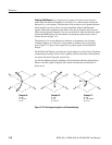
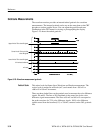
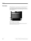
The Jitter measurement uses a demodulator method to determine signal jitter. The
serial clock is recovered from the input signal and multiplied (demodulated)
against a very stable oscillator, which translates any phase modulation (jitter) into
a DC value. The resulting DC values plotted against time is proportional to jitter
in the serial signal. This jitter waveform is passed through a high-pass filter and
applied to a peak detector. The peak detector measurement is presented in the
jitter measurement box seen in Figure 3–27. The demodulator can detect jitter up
to 5 MHz.
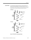
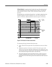
The Jitter measurement lets you pick one of four high-pass filters and set the
readout units. Press the CONFIG MENU button and select JITTER. Use the
JITTER HPF bezel button to select from the available filters: 10 Hz, 1 kHz,
10 kHz, and 100 kHz. The jitter readout displays in seconds (SEC) or unit
intervals (UI). Use the READOUT bezel button select the unit type or turn off
the readout.
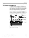
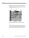
You can display the jitter waveform using any of the LINE/FIELD sweep
selections. You can also use the Line Select function to view an individual line.
Vertical Gain and horizontal MAG are available to enhance your view of the
jitter waveform. Use the Voltage Cursors to measure specific parts of the jitter
waveform. The Jitter Config menu READOUT selection determines the units for
the Voltage Cursors.
Jitter Demodulation
Jitter Measurement
Configuration