Reference
3–6
WFM 601A, WFM 601E & WFM 601M User Manual
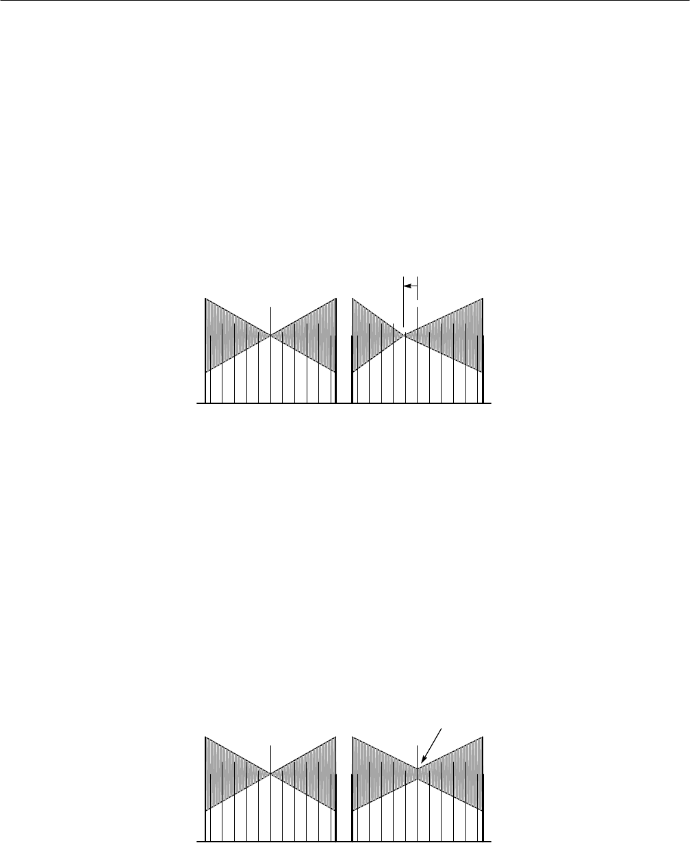
The timing measurement is based on alignment of the center marker and the null
point at the center of the waveform. The generator provides a center marker,
which is centered on the null point when interchannel timing is correct. A shift of
the null to the left or right indicates a difference in the relative timing. If the null
shifts two full time markers, the relative timing error between channels would be
40 ns. If the null is to the left of the center marker, the color difference channel is
advanced relative to the luminance channel. When either of the nulls is shifted to
the right, that color difference signal is delayed relative to the luminance channel.
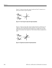
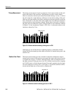
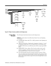
In Figure 3–9, the chrominance channel—CH 3 (Pr)—is advanced relative to the
luminance channel by 20 ns.
Shifted null point
Figure 3–9: Bowtie waveform showing a timing error in CH 3
Although you can use Waveform or Lightning displays to determine channel
timing, the Bowtie method provides better resolution of channel timing and is the
easiest to use.
The bowtie measurement provides a method to determine whether the relative
channel gain is correct. If the gains are not equal, the center null point will not be
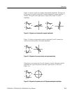
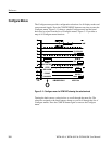
a complete null. Figure 3–10 shows a Bowtie display with an incomplete null in
the right waveform. If the gain error is in CH 1, neither waveform has a complete
null. If CH 2 gain is off, the left waveform will not null completely, but the right
one will. If the gain is off for CH 3, as in Figure 3–10, the left waveform will be
normal and the right one will not reach a complete null.
Incomplete null
Figure 3–10: Bowtie waveform showing gain error in CH 3
Timing Measurement
Relative Gain Check


