


Reference
3–10
WFM 601A, WFM 601E & WFM 601M User Manual
GAMUT. Configures conditions and error indicators for the gamut error alarm.
H GAMUT CHECK. Determines whether RGB, Composite (CMPST), or both
types of gamut errors trigger the gamut alarm. RGB indicates when the R, G,
or B signals are less than 0 mV or greater than 700 mV. CMPST indicates
when the sum of luminance and peak chrominance exceed the level selected
with GAMUT (IRE). Use ALARM DISP to determine the indicator of the
gamut alarm.
H ALARM DISP. Determines how the gamut alarm is indicated. In SCREEN
mode, a gamut error message appears in the lower left of the CRT. In PIX
MON mode, the portion of the video picture that exceeds gamut, blinks in a
highlighted or bright-up mode on the picture monitor output.
H GAMUT. Sets the level used for the CMPST gamut alarm. For NTSC, the
levels are 100, 110, 120 and 131 IRE. For PAL, the levels are 700 mV and
950 mV. Use GAMUT CHECK to pick the CMPST alarm.
H LIMIT FORMAT. Determines if the gamut limit check is for PAL or NTSC
format signals. AUTO mode automatically determines the input format.
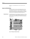
EYE PATTERN. Selects the display mode and attenuation of low-frequency jitter
for the EYE and EQ EYE display modes.
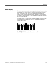
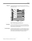
H MODE. Selects between OVERLAY and 10-EYE trigger modes. Overlay
displays all bits of a serial word at each eye location. The 10-EYE mode
displays all ten bits of the serial signal at ten fixed locations.
H CLOCK BW. Selects between 10 Hz, 100 Hz, and 1 kHz filters to suppress
low-frequency jitter.
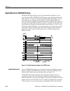
JITTER. Configures the Jitter measurement with a high pass filter and the units of
the readout.
H JITTER HPF. Selects from high pass filters 10 Hz, 1 kHz, 10 kHz, and
100 kHz. The selection appears in the jitter readout box and in the upper
right corner of the CRT, just below the horizontal deflection factor.
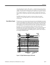
H READOUT. Determines whether the jitter measurement is in the units UI
(unit intervals) or seconds or if the readout is off.