


Instruction Manual
IM-106-340, Rev. 4.0
May 2006
8-5
Oxymitter 4000
A Potter & Brumfield R10S-E1Y1-J1.0K 3.2 mA DC or an equal interposing
relay will be mounted where the contact wires terminate in the control/relay
room.
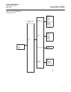
If autocalibration systems are utilized, the bidirectional logic contact is utilized
as a "hand-shake" signal between the autocalibration system (SPS 4001B or
IMPS 4000) and is unavailable for alarming purposes. Additional contacts are
provided through the autocalibration systems, noted below.
SPS 4001B and IMPS 4000, 1-4 probes
• One contact closure per probe from the control room to the SPS 4001B
or IMPS 4000 for "calibration initiate".
• One contact output per probe from the SPS 4001B or IMPS 4000 to the
control room for "in calibration" notification.
• One contact output per probe from the SPS 4001B or IMPS 4000 to the
control room for "calibration failed" notification. (Includes output from
pressure switch indicating "cal gas bottles empty").
Additional IMPS 4000 Alarm Contacts
• One contact per IMPS 4000 for "low calibration gas flowing".
• One contact per IMPS 4000 for "high calibration gas flowing".
NOTE
The 4-20 mA signal can be configured to respond normally during any
calibration, or can be configured to hold the last O
2
value upon the initiation of
calibration. Factory default is for the 4-20 mA signal to operate normally
throughout calibration.
NOTE
Holding the last O
2
value may be useful if several probes are being averaged
for the purpose of automatic control. Unless several probes are being
averaged, always place any control loops using the O
2
signal into manual
prior to calibrating.
IDENTIFYING AND
CORRECTING ALARM
INDICATIONS
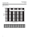
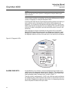
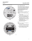
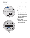
For an Oxymitter 4000 with a membrane keypad, faults are indicated by four
diagnostic, or unit, alarm LEDs. A pattern of repeating blinks define the
problem. A condensed table of the errors and the corresponding blink codes
can be found on the inside right cover of the electronics housing. Table 8-1
also identifies the blink code and fault status of each LED as well as the
output of the 4-20 mA signal line and a fault number that corresponds to the
troubleshooting instructions provided in this section.
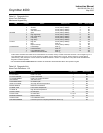
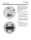
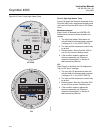
For an Oxymitter 4000 with the optional LOI, alarm messages are displayed
on the LOI display window when the alarm status display is accessed via the
LOI menu. A listing of the alarm/fault messages and the related fault status
descriptions and fault numbers are shown in Table 8-2.