


Instruction Manual
IM-106-340, Rev. 4.0
May 2006
1-9
Oxymitter 4000
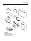
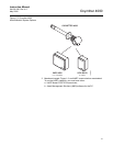
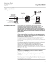
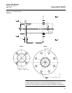
Figure 1-7. Oxymitter 4000
HART Communications and
AMS Application
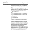
System Considerations Prior to installing your Oxymitter 4000, make sure you have all the
components necessary to make the system installation. Ensure all the
components are properly integrated to make the system functional.
After verifying that you have all the components, select mounting locations
and determine how each component will be placed in terms of available line
voltage, ambient temperatures, environmental considerations, convenience,
and serviceability.
Figure 1-7 shows a typical system wiring.
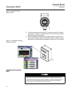
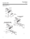
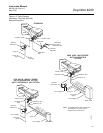
A typical system installation for an Oxymitter 4000 with integral electronics is
shown in Figure 1-8. A typical system installation for an Oxymitter 4000 with
remote electronics is shown in Figure 1-9.
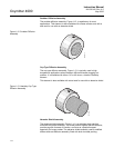
A source of instrument air is optional at the Oxymitter 4000 for reference
air use. Since the unit is equipped with an in place calibration feature,
provisions can be made to permanently connect calibration gas bottles to the
Oxymitter 4000.
If the calibration gas bottles will be permanently connected, a check valve is
required next to the calibration fittings on the integral electronics.
This check valve is to prevent breathing of the calibration gas line and
subsequent flue gas condensation and corrosion. The check valve is in
addition to the stop valve in the calibration gas kit or the solenoid valves in the
IMPS 4000 or SPS 4001B.
NOTE:
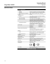
The electronics is rated NEMA 4X (IP66) and is capable of operation at
temperatures up to 185°F (85°C).
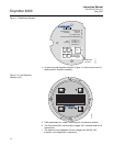
The optional LOI is also rated for operation at temperatures up to 185°F
(85°C). The infrared keypad functionality will degrade at temperatures above
158°F (70°C).
Retain the packaging in which the Oxymitter 4000 arrived from the factory in
case any components are to be shipped to another site. This packaging has
been designed to protect the product.
37260005
4-20 mA Output
(Twisted Pairs)
2 Calibration Gas Lines
by Customer
[ ( ) max]300 ft 90 m
HART
Model 275/375
Handheld
Interface
Termination in
Control Room
Asset Management Solutions
Line Voltage
Hazardous Area
Oxymitter 4000
with Integral Electronics