


Oxymitter 4000
2-10
Instruction Manual
IM-106-340, Rev. 4.0
May 2006
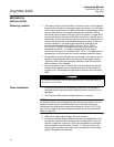
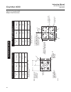
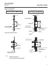
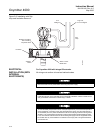
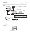
Figure 2-8. Installation with Drip
Loop and Insulation Removal
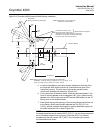
ELECTRICAL
INSTALLATION (WITH
INTEGRAL
ELECTRONICS)
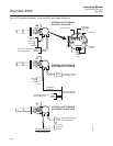
For Oxymitter 4000 with Integral Electronics
All wiring must conform to local and national codes.
P
S
U
E
I
T
P
I
C
R
H
W
E
N
T
H
G
C
K
E
N
I
-
E
E
R
W
A
V
I
S
O
L
P
-
X
O
M
T
A
G
N
I
N
-
R
I
T
L
A
I
V
E
-
E
E
H
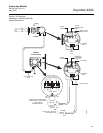
GAS
CAL.
Drip
Loop
Logic I/O,
4-20 mA Signal
Line
Voltage
Replace Insulation
after Installing
Oxymitter 4000
Insulation
Adapter
Plate
Stack or Duct
Metal Wall
29340005
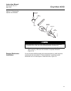
Disconnect and lock out power before connecting the power supply.
Install all protective covers and safety ground leads after installation. Failure to install covers
and ground leads could result in serious injury or death.
To meet the Safety Requirements of IEC 1010 (EC requirement), and ensure safe operation
of this equipment, connection to the main electrical power supply must be made through a
circuit breaker (min 10 A) which will disconnect all current-carrying conductors during a fault
situation. This circuit breaker should also include a mechanically operated isolating switch.
If not, then another external means of disconnecting the supply from the equipment should
be located close by. Circuit breakers or switches must comply with a recognized standard
such as IEC 947.