


Oxymitter 4000
4-4
Instruction Manual
IM-106-340, Rev. 4.0
May 2006
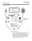
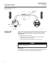
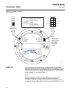
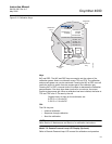
Figure 4-2. Defaults - Oxymitter
4000 with LOI
LOGIC I/O This two-terminal logic contact can be configured either as a solid-state
relay-activated alarm or as a bi-directional calibration handshake signal to an
IMPS 4000 or SPS 4001B. The configuration of this signal depends on the
setting of the LOGIC I/O PIN MODE via HART/AMS or LOI. The ten different
modes available are explained in Table 4-1.
Alarm
When configured as an alarm, this signal alerts you to an out-of-spec
condition. The output is +5 Vdc in series with a 340 ohm resistor.
For optimum performance, Rosemount Analytical recommends connecting
the output to a Potter & Brumfield 3.2 mA DC relay (P/N R10S-E1Y1-J1.0K).
37260012
SW2
SW1
1
2
3
4
TP1
J1
TP2
TP3
RED
YEL
GRN
ORG
TP4
TP5
TP6
4-20 mA
is internally
powered
(Default)
4-20 mA requires
external power
HART
0 to 10% O
2
3.5 mA
220 V 115 V
0 to 25% O
2
Local
21.6 mA
Default
position
(Ex-factory)
3.5 mA/21.6 mA
0to25%O:
2
0to10%O/
2
Local:
HART:
O Range set by HART/AMS
(From 0 to 40% O )
O Range set by Pos 2
O Range
When alarm exists, or
on power up, current
output goes to this value
2
2
2
2
ON
OFF
Note:
The 115 V option
at switch SW2
position 4 is active
only when the
heater voltage
option is set to
manual in the
software.