


Instruction Manual
IM-106-340, Rev. 4.0
May 2006
2-3
Oxymitter 4000
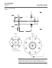
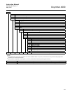
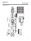
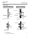
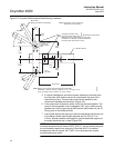
Figure 2-1. Oxymitter 4000
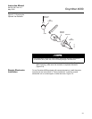
Probe Installation
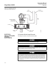
Cover Removal and Access
(305)
(305)
12
12
Add to Dim “A”
for probe with
Ceramic Diffuser
and Flame
Arrestor
5.14(131)
With
Standard
Snubber
Diffuser
Dim "A"
Add to Dim “A”
for probe
with Ceramic
Diffuser
Dim "B”
Removal Envelope
Elec Conn
3/4 NPT
ANSI 1/4 (6.35) Tube
DIN 6 mm Tube
Bottom View
P
S
U
E
I
T
P
I
C
R
H
W
E
N
T
H
G
C
K
E
N
I
-
E
E
R
W
A
V
I
S
O
L
P
-
X
O
M
T
A
G
N
I
N
-
R
I
T
L
A
I
V
E
-
E
E
H
4.77 (121)
6.02 (153)
12.50 (318)
GAS
CAL.
500 VA
R
SERIAL NO.
TAG NO.
OXYMITTER 4000
VOLTS: WATTS:
OUTPUT: LINE FUSE:
Rosemount Analytical Inc.
Orrville, OH 44667-0901
85-264 VAC 48-62 Hz
TM
800-433-6076
4-20 mA
R
5 Amps
TM
HART
SMART FAMILY
REF.
GAS
-
-
R
H
G
T
I
N
E
W
H
C
I
T
K
E
P
E
A
I
T
C
U
E
V
L
I
-
M
N
I
N
L
O
A
R
P
N
I
X
E
-
W
G
E
S
I
V
A
T
O
S
E
H
E
R
P
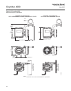
6.52
(166)
2.89
(73)
1.55
(39)
3.80(96)
Process flow must be in
this direction with respect
to deflector 3534B48G01
Dia Max
2.27 (58)
Insulate if exposed to
Ambient weather conditions
Dimensions are in
inches with millimeters
in parentheses.
Note:
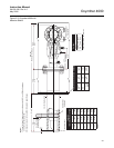
3535B18H02
3535B45H01
DIN
ANSI
0.062 THK Gasket
Hole
Flange
(4) Holes
Eq Sp
on BC
Dia
Dia
DIN
ANSI
4512C19H01
4.75
(121)
4512C17H01
6.00
(153)
(20)
0.75
(145)
5.71
(18)
0.71
7.28
(185)
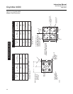
DIM "A"
3ft
9ft
6ft
PROBE
18 in.
12 ft
DIM "B"
(2179)
85.8
(3094)
121.8
(4008)
157.8
(3607)
142
(2692)
106
70
(1778)
(864)
34
(1265)
49.8
(808)
31.8
(406)
16
36920001
15 ft
(4923)
193.8
(4521)
178
18 ft
(5837)
229.8
(5436)
214
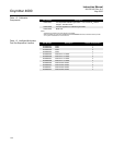
Table 1. Mounting Flange
Table 2. Installation/Removal
Ref Air
Cal Gas