


Instruction Manual
IM-106-340, Rev. 4.0
May 2006
8-11
Oxymitter 4000
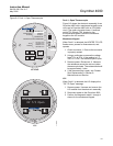
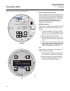
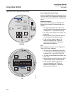
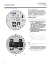
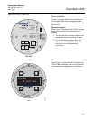
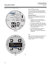
Figure 8-7. Fault 5, Open Heater
Fault 5, Open Heater
Figure 8-7 shows the electronic assembly for an
Oxymitter 4000 with a membrane keypad (upper
view) and a Oxymitter 4000 with an LOI (lower
view).
Membrane Keypad
When Fault 5 is detected, the HEATER LED
flashes once, pauses for three seconds, and
repeats.
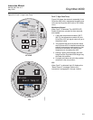
1. Remove power.
2. Remove the electronic assembly per
"Electronic Assembly Replacement" in
Section 9: Maintenance and Service.
3. Using a multimeter, measure the resistance
across the terminals of heater connector,
J8.
4. The measurement should be approxi-
mately 72 ohms. If the heater is open, see
"Heater Strut Replacement" in Section 9:
Maintenance and Service.
LOI
When Fault 5 is detected, the LOI displays the
"O2 Heater Open" message.
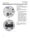
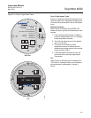
1. Remove power. Unscrew and remove the
LOI module from the electronic assembly.
2. Perform the diagnostic steps 2 through 4
shown for the membrane keypad.
37260023
LOI
KEYPAD
Alarms
O2 Heater Open
DIAGNOSTIC
ALARMS
TEST
POINTS
HEATER T/C
HEATER
O2 CELL
CALIBRATION
CALIBRATION RECOMMENDED
O2 CELL mV +
O2 CELL mv -
HEATER T/C +
HEATER T/C -
INC INC
DEC DEC
HIGH
GAS
LOW
GAS
CAL
TEST GAS +
PROCESS -
% O2
SW2
TP1
J1
TP2
TP3
RED
YEL
GRN
ORG
TP4
TP5
TP6
ON