


Oxymitter 4000
9-12
Instruction Manual
IM-106-340, Rev. 4.0
May 2006
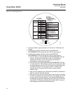
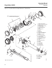
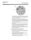
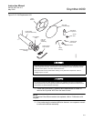
Electronic Assembly Replacement
(Figure 9-5)
1. Remove the right housing cover uncovering the electronic assembly.
2. Depress and remove the J1 (cell and T/C) connector from the J1 socket.
Loosen the three captive mounting screws (16, Figure 9-3 or Figure 9-4)
on the microprocessor board (top board).
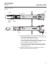
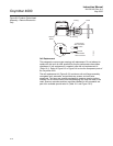
3. The J8 connector (heater leads) can be accessed by moving the J1 con-
nector leads out of the slot on microprocessor board (17) and sliding the
electronic assembly (12) partially out of the housing (Figure 9-6).
4. Squeeze the J8 connector on the sides and carefully remove. The elec-
tronic assembly can now be completely removed from the housing.
5. Reconnect the J8 connector to the power supply board. Make sure the
connector is secure.
6. Holding the J1 connector leads, slide the electronic assembly the rest of
the way into the housing. Align the electronic assembly so that it fits
flush on the pins. To ensure that it is flush, gently try to rotate the elec-
tronics. If the electronics rotates, repeat the alignment.
7. Reconnect the J1 connector to the microprocessor board. Ensure the
connector is secure and tighten the three captive mounting screws on
the microprocessor board (top board).
8. Replace the housing cover and ensure it is tight.
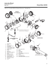
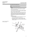
Terminal Block Replacement
1. Unscrew left housing cover (27, Figure 9-3).
2. Loosen mounting screws (26) on terminal block (25) and carefully lift the
block out of the housing.
3. Carefully align the new terminal block on the pins so that it sits flat in the
housing. The round end of the terminal block should be on the opposite
side of the housing conduit ports and should not be able to rotate.
4. Tighten the three mounting screws and ensure the terminal block is
secure in the housing.
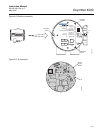
Fuse Replacement
(Figure 9-7)
1. Remove the right housing cover uncovering the electronic assembly.
2. Depress and remove the J1 (cell and T/C) connector from the J1 socket.
Loosen the three captive mounting screws (16, Figure 9-3 or Figure 9-4)
on the microprocessor board (top board).
3. The J8 connector (heater leads) (Figure 9-6) can be accessed by mov-
ing the J1 connector leads out of the slot on the microprocessor board
(17, Figure 9-3 or Figure 9-4) and sliding the electronic assembly (12)
partially out of the housing.
4. Squeeze the J8 connector on the sides and carefully remove. The elec-
tronic assembly can now be completely removed from the housing.
5. Completely remove the three mounting screws (16) on the microproces-
sor board (17).