


Oxymitter 4000
2-14
Instruction Manual
IM-106-340, Rev. 4.0
May 2006
b. Calibration Handshake/Logic I/O. The output can either be an alarm
or provide the handshaking to interface with an IMPS 4000 or
SPS 4001B. For more information, refer to "Logic I/O" in Section 4:
Configuration of Oxymitter 4000 with LOI, and either the IMPS 4000
Intelligent Multiprobe Test Gas Sequencer Instruction Manual or the
SPS 4001B Single Probe Autocalibration Sequencer Instruction
Manual.
c. If autocalibration is not utilized, a common bi-directional logic contact
is provided for any of the diagnostic alarms listed in Table 8-1. The
assignment of alarms which can actuate this contact can be modified
to one of seven additional groupings listed in Table 4-1.
The logic contact is self-powered, +5 VDC, 340 ohm series
resistance. An interposing relay will be required if this contact is to be
utilized to annunciate a higher voltage device, such as a light or
horn, and may also be required for certain DCS input cards. A Potter
& Brumfield R10S-E1Y1-J1.0K 3.2 mA DC or an equal interposing
relay will be mounted where the contact wires terminate in the
control/relay room.
4. Install cover (27, Figure 9-4).
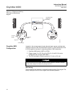
5. Install Interconnecting Cable.
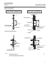
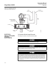
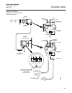
a. Remove cover (3) from junction box (5). Connect the electronics end
of the interconnecting cable to the "FROM PROBE" side of the
terminal block (Figure 2-10).
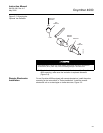
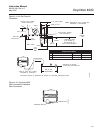
b. Remove housing cover (27).
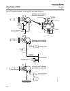
c. Connect the heater power leads, the thermocouple leads and the
oxygen signal leads at the terminal block. The leads are tagged for
polarity.