


Instruction Manual
IM-106-340, Rev. 4.0
May 2006
ix
Oxymitter 4000
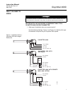
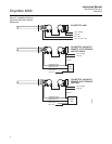
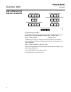
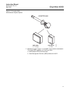
Figure 3. Oxymitter 4000 without
SPS 4001B Wiring Diagram
QUICK REFERENCE
GUIDE MANUAL
CALIBRATION
INSTRUCTIONS
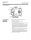
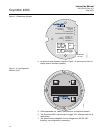
Performing a Manual Calibration with a Membrane Keypad
1. Place the control loop in manual.
2. Press the CAL key. The CAL LED will light solid.
3. Apply the first calibration gas.
4. Press the CAL key. When the unit has taken the readings using the first
calibration gas, the CAL LED will flash continuously.
5. Remove the first calibration gas and apply the second calibration gas.
6. Push the CAL key. The CAL LED will light solid. When the unit has
taken the readings using the second calibration gas, the CAL LED will
flash a two-pattern flash or a three-pattern flash. A two-pattern flash
equals a valid calibration, three-pattern flash equals an invalid
calibration.
7. Remove the second calibration gas and cap off the calibration gas port.
8. Press the CAL key. The CAL LED will be lit solid as the unit purges.
When the purge is complete, the CAL LED will turn off.
9. If the calibration was valid, the DIAGNOSTIC ALARMS LEDs indicate
normal operation. If the new calibration values are not within the
parameters, the DIAGNOSTIC ALARMS LEDs will indicate an alarm.
10. Place the control loop in automatic.
AC L1
AC N
+
+
-
-
4-20
Terminal
Block
AC Line
Voltage Port
Signal
Port
Left Side of
Oxymitter 4000
4-20 mA
Signal
29770003
AC Terminal
Cover
Line Voltage
(85 to 264 VAC)
Ground
Lugs
Logic I/O