


Oxymitter 4000
6-10
Instruction Manual
IM-106-340, Rev. 4.0
May 2006
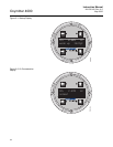
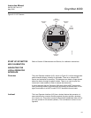
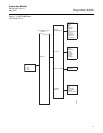
OXYMITTER 4000 TEST
POINTS
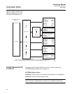
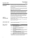
Refer to Figure 6-6. System test points are located on the board below the
LOI module. Test points 1 through 6 allow you to monitor with a multimeter:
the heater thermocouple, the O
2
cell millivolt, and the process O
2
.
• TP1 and TP2 monitor the oxygen cell millivolt output which equates to
the percentage of oxygen present.
• TP3 and TP4 monitor the heater thermocouple.
• TP5 and TP6 monitor the process gas or the calibration gas parameter.
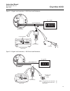
REMOTE POWERED
LOOP LCD DISPLAY
(OPTIONAL)
Refer to Remote Powered Loop LCD manual for calibration and operation.
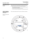
Figure 6-6. Oxymitter 4000 -
Test Poi nts
37260037
TP1
J1
TP2
TP3
RED
YEL
GRN
ORG
TP4
TP5
TP6