


Instruction Manual
IM-106-340, Rev. 4.0
May 2006
Oxymitter 4000
http://www.processanalytic.com
Section 8 Troubleshooting
Overview . . . . . . . . . . . . . . . . . . . . . . . . . . . . . . . . . . . . . . . page 8-1
General . . . . . . . . . . . . . . . . . . . . . . . . . . . . . . . . . . . . . . . . page 8-3
Alarm Indications . . . . . . . . . . . . . . . . . . . . . . . . . . . . . . . . page 8-3
Alarm Contacts . . . . . . . . . . . . . . . . . . . . . . . . . . . . . . . . . . page 8-4
Identifying and Correcting Alarm Indications . . . . . . . . . page 8-5
Calibration Passes, but Still Reads Incorrectly . . . . . . . . page 8-22
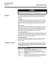
OVERVIEW While the Oxymitter 4000 electronics provides a significant number of
diagnostic alarms to assist in troubleshooting potential problems, it is good to
place these alarms in perspective with respect to the instrument's operating
principles:
When the Zirconium Oxide sensing cell is heated to its setpoint [1357°F
(736°C)], the cell will generate a voltage that represents the difference
between the process O
2
% and the reference O
2
% inside the probe (20.95%
O
2
ambient air).
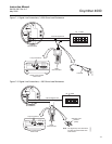
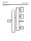
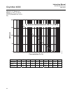
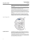
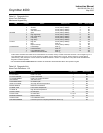
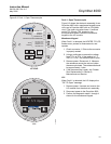
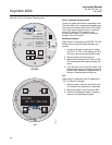
Test points, Figure 8-1, are provided to read the raw millivolt value generated
by the thermocouple that controls the cell temperature and also the raw cell
signal.
The cell temperature at test points 3 and 4 should always be stable at
approximately 29 to 30 millivolts, which represents the [1357°F (736°C)]
setpoint temperature.
When flowing calibration gasses, the raw cell millivolt value at test points 1
and 2 should represent the levels on the chart in Figure 8-1. Note that the raw
cell millivolt value increases logarithmically as the O
2
concentration
decreases.