


Oxymitter 4000
9-14
Instruction Manual
IM-106-340, Rev. 4.0
May 2006
Heater Strut Replacement
This paragraph covers heater strut replacement. Do not attempt to replace the
heater strut until all other possibilities for poor performance have been
considered. If heater strut replacement is needed, order a replacement heater
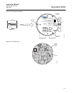
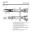
strut (Table 10-1). Refer to Figure 9-3 or Figure 9-4 to view the component
parts of the Oxymitter 4000.
1. Follow the instructions in "Removal and Replacement of Probe" to
remove the Oxymitter 4000 from the stack or duct.
2. For a unit with integral electronics, disconnect electronics per "Replace
Entire Integral Electronics (with Housing)", steps 2 through 5.
3. For a unit with remote electronics, remove cover (11, Figure 9-4) from
housing (21) along with adapter board (8) and screw (9) from heater
strut assembly (1, Figure 9-3).
4. Remove four screws (2, Figure 9-4). Remove the probe from housing
(21).
5. Remove tube clamps (29, Figure 9-3) and silicon tubes (28, Figure 9-3)
from the CAL and REF gas ports and the CAL and REF gas lines.
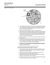
6. Loosen, but do not remove, three screws (30, Figure 9-3). The spring
tension will release and the heater strut assembly should move up.
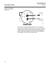
7. When the spring tension is released, remove three screws (30). Grasp
the wire loop and carefully slide the heater strut assembly (Figure 9-8)
out of the probe tube.
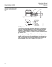
8. When replacing the strut, orient the probe so the small calibration gas
tube is at the 6 o'clock position of the probe tube. Align the slot on the
heater plate with the calibration gas line in the probe tube. Slide the strut
into the probe tube. It will turn to align the hole on the back plate of the
strut with the calibration gas line. When the hole and the calibration gas
line are aligned correctly, the strut will slide in the rest of the way.
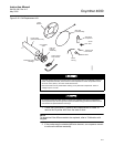
9. As the strut installation nears completion, install the guide rod into the
calibration gas tube to assist in guiding the calibration gas tube through
the hole in the end of the strut.
10. Push down on the back plate of the strut to make sure you have spring
tension and then tighten the three screws on the back plate.
11. Replace the CAL and REF gas silicon tubes.
12. For units with integral electronics, install the entire electronics per
"Replace Entire Integral Electronics (with Housing)", steps 7 through 13.
Use heat resistant gloves and clothing when removing probe. Do not attempt to work on the
probe until it has cooled to room temperature. The probe can be as hot as 800°F (427°C).
This can cause severe burns.