


Oxymitter 4000
6-6
Instruction Manual
IM-106-340, Rev. 4.0
May 2006
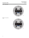
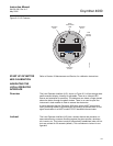
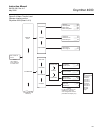
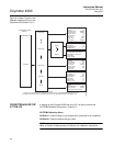
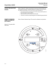
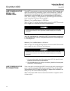
Figure 6-4. Menu Tree for Local
Operator Interface (LOI) on the
Oxymitter 4000 (Sheet 2 of 2)
OXYMITTER 4000 SETUP
AT THE LOI
In setting up the Oxymitter 4000 from the LOI, it is best to start at the
SYSTEM/Calibration Setup menu, Figure 6-4.
SYSTEM/Calibration Setup
O2 Gas #1 - Enter the high or low cal gas value (the order is not important).
O2 Gas #2 - Enter the second cal gas value.
NOTE
Refer to Section 9: Maintenance and Service, for calibration instructions.
SYSTEM
O2 Gas 1
O2 Gas 2
O2-Reset Vals
O2
O2 Cal Intervl
O2-
Gas Time
Purge Time
_____%
_____%
____H
___Sec.
Yes/No
Yes/No
____H
___Sec.
Yes/No
Out Tracks
Next Cal
Auto Calib?
O2 Type
O2 Range
O2 Alarm Leve
_______
______%
l _____mA
Do O2 Trim
Calib Setup
Input/Output
Parameters
Status
Software
37260018
(CONTINUED FROM
SHEET 1)
Analog
Digital
NOTE
In column four of this menu, the selections in are user configurable. text selections are
procedures; related instructions are displayed on the LOI. All other parameters are display only.
Italics Bold
Version xxx
Checksum xxx
Build Number xxx
Build Date xxxxxx
Test Code xx
SW Err File xx
SW Err Line xx
Alarms __________
PID Parameters 115/220
Yes/No
(Cal. required after reset)
Reset Device?
O2 Slope
O2 Constant
O2 T90 Time
Auto Tune?
Lockout Time
Revert Time
Luminance
____ mV/D
____ mV
0:00
Yes/No
0:00
0:00
______
Logic IO Mode
Low O2 Alarm
Input State
Force Output
See Table 4-1
See “Abort
Calibration” in Section 9.