


Oxymitter 4000
4-2
Instruction Manual
IM-106-340, Rev. 4.0
May 2006
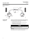
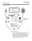
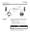
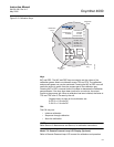
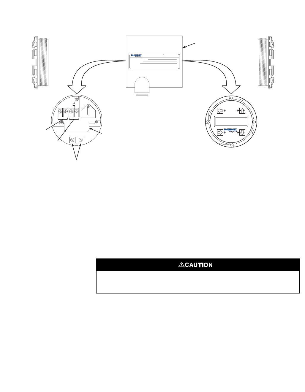
Figure 4-1. Electronics Housing
Terminals with LOI
Oxymitter 4000
Configuration
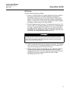
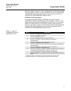
Located on the microprocessor board are two switches that configure outputs
(Figure 4-2). To access these switches, the LOI module must be removed.
SW1 determines if the 4-20 mA signal is internally or externally powered.
SW2 determines:
1. Range control, HART or LOCAL.
2. Oxygen range, 0 to 10% O
2
or 0 to 25% O
2
. (0 to 40% O
2
is also
configurable only through HART/AMS.)
3. The 4-20 mA signal, at fault or power up, 3.5 mA or 21.6 mA.
SW1 Setting
The two settings are internally or externally powering the 4-20 mA signal. The
factory setting is for the 4-20 mA signal to be internally powered.
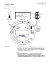
37260011
AC L1
AC N
+
+
-
-
4-20
500 VA
SERIAL NO.
TAG NO.
OXYMITTER 4000
WATTS:VOLTS:
FUSE:LINE
OUTPUT:
Rosemount Analytical Inc.
Orrville, OH 44667-0901
85-264 VAC 48-62 Hz
TM
800-433-6076
4-20 mA
R
5 Amps
TM
HART
SMART FAMILY
4-20 mA
Signal
Logic I/O
Ground Lugs
Terminal
Block
Oxymitter 4000
Electronics
Housing
LOI
Remove power before changing defaults. If defaults are changed under power, damage to
the electronics package may occur.