


Instruction Manual
IM-106-340, Rev. 4.0
May 2006
8-3
Oxymitter 4000
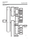
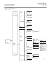
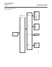
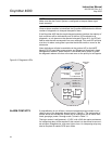
GENERAL The troubleshooting section describes how to identify and isolate faults that
may develop in the Oxymitter 4000. When troubleshooting, reference the
following.
Grounding
It is essential that adequate grounding precautions are taken when installing
the system. Thoroughly check both the probe and electronics to ensure the
grounding quality has not degraded during fault finding. The system provides
facilities for 100% effective grounding and the total elimination of ground
loops.
Electrical Noise
The Oxymitter 4000 has been designed to operate in the type of environment
normally found in a boiler room or control room. Noise suppression circuits
are employed on all field terminations and main inputs. When fault finding,
evaluate the electrical noise being generated in the immediate circuitry of a
faulty system. Ensure all cable shields are connected to earth.
Loose Integrated Circuits
The Oxymitter 4000 uses a microprocessor and supporting integrated circuits
(IC). If the electronics are handled roughly during installation or located where
subjected to severe vibration, the ICs could work loose. Before troubleshoot-
ing the system, ensure all ICs are fully seated.
Electrostatic Discharge
Electrostatic discharge can damage the ICs used in the electronics. Before
removing or handling the processor board or the ICs, ensure you are at
ground potential.
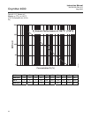
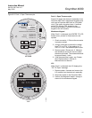
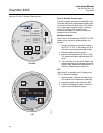
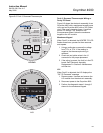
ALARM INDICATIONS The first indication of a problem at the analyzer usually comes from the Oper-
ators running the process. Critical alarms that render the O
2
measurement
unusable will force the 4-20 mA analog output signal representing O
2
to go to
a default condition, as follows:
Install all protective equipment covers and safety ground leads after troubleshooting. Failure
to install covers and ground leads could result in serious injury or death.
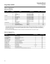
4-20 mA Signal Alarm Levels
4-20 mA signal Analyzer Condition
0 mA Analyzer unpowered, or completely failed
3.5 mA Critical Alarm - analyzer reading unusable (factory default)
3.8 mA
Reading Under Range (Example - user sets range to 2-10%. Current
reading is 1.9%)
4 to 20 mA Normal Operation
20.5 mA Reading Over Range (Example - range is 0-10%. Current reading is 12%)
>21 mA
Critical Alarm - analyzer reading is unuasble (user can choose this alarm
level instead of the factory default level of 3.5 to 3.6 mA)