


Instruction Manual
IM-106-340, Rev. 4.0
May 2006
2-17
Oxymitter 4000
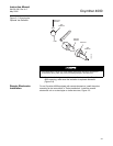
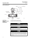
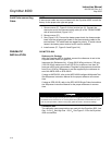
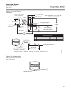
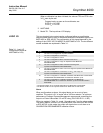
Figure 2-11. Air Set, Plant Air
Connection
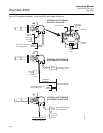
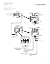
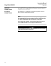
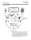
Figure 2-12. Oxymitter 4000
Gas Connections Calibration
Gas Connections
To Electronics
Ref Air Set
263C152G01
1 Flowmeter 0.2-2.0 scfh 771B635H02
2 2" Pressure Gage 0-15 psig 275431-006
3 Combination Filter-Reg. 0-30 psig 4505C21G01
Note: Dimensions are in inches with
millimeters in parentheses.
1
2
3
4.81 (122,17)
Flow Set
Point Knob
0.125-27 NPT Female
Outlet Connection
1.19
(30,22)
10.0
(254)
REF
Drain Valve
3.12 (79,25) Max
8.50
(215,90)
Max
2.0
(50,80)
2 Mounting Holes
3.19 (81,03) Lg
through Body for
0.312 (7,92) Dia Bolts
1.50
(38,10)
2.250 (57,15)
Schematic Hookup for Reference Air Supply on Oxymitter 4000 Probe Head.
Outlet
0.25-18 NPT Female
Inlet Connection
Instrument Air Supply
10-225 psig Max Pressure
26170035
0.250 or 6 mm O.D. Tubing
(Supplied by Customer)
500 VA
SERIAL NO.
TAG NO.
OXYMITTER 4000
WATTS:VOLTS:
FUSE:LINEOUTPUT:
Rosemount Analytical Inc.
Orrville, OH 44667-0901
85-264 VAC 48-62 Hz
TM
800-433-6076
4-20 mA
R
5 Amps
TM
HART
SMART FAMILY
Replacement Parts
500 VA
R
SERIAL NO.
TAG NO.
OXYMITTER 4000
VOLTS: WATTS:
OUTPUT: LINE FUSE:
RosemountAnalytical Inc.
Orrville,OH44667-0901
85-264 VAC 48-62Hz
TM
800-433-6076
4-20 mA
R
5Amps
TM
HART
SMART FAMILY
Calibration Gas
Reference Air
26170025