


Instruction Manual
IM-106-340, Rev. 4.0
May 2006
Oxymitter 4000
http://www.processanalytic.com
Section 3 Configuration of Oxymitter 4000
with Membrane Keypad
Verify Installation . . . . . . . . . . . . . . . . . . . . . . . . . . . . . . . . page 3-1
Logic I/O . . . . . . . . . . . . . . . . . . . . . . . . . . . . . . . . . . . . . . . page 3-5
VERIFY INSTALLATION
Mechanical Installation Ensure the Oxymitter 4000 is installed correctly. See Section 2: Installation.
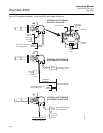
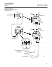
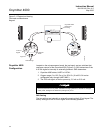
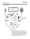
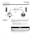
Terminal Block Wiring 1. Remove cover (27) to expose terminal block (25).
2. Check the terminal block wiring (Figure 3-1). Be sure the power,
4-20 mA signal, and the logic outputs are properly connected and
secure. To avoid a shock hazard, the power terminal cover must be
installed. For units with remote electronics, check the terminal block
wiring at the probe and at the remote electronics unit.
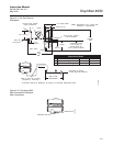
3. Install housing cover (27, Figure 9-3 or Figure 9-4) on terminal block
(25).
Install all protective equipment covers and safety ground leads before equipment startup.
Failure to install covers and ground leads could result in serious injury or death.