


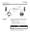

Oxymitter 4000
3-4
Instruction Manual
IM-106-340, Rev. 4.0
May 2006
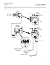
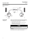
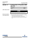
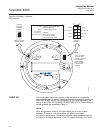
Figure 3-2. Defaults - Oxymitter
4000 with Membrane Keypad
Read O
2
Concentration
Once the cell is up to operating temperature, the O
2
percentage can be read:
1. Access TP5 and TP6 next to the membrane keypad. Attach a
multimeter across TP5 and TP6. The calibration and process gases can
now be monitored. Pressing the INC or DEC once will cause the output
to switch from the process gas to the calibration gas. Pressing INC or
DEC a second time will increase or decrease the calibration gas
parameter. If the keys have been inactive for one minute, the output
reverts to the process gas. If the keys have been inactive for one
minute, the output reverts to the process gas.
37260010
DIAGNOSTIC
ALARMS
TEST
POINTS
HEATER T/C
HEATER
O2 CELL
CALIBRATION
CALIBRATION RECOMMENDED
O2 CELL mV +
O2 CELL mV -
HEATER T/C +
HEATER T/C -
INC INC
DEC DEC
HIGH
GAS
LOW
GAS
CAL
TEST GAS +
PROCESS -
% O2
SW2
SW1
TP1
J1
TP2
TP3
RED
YEL
GRN
ORG
TP4
TP5
TP6
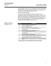
ON
4-20 mA
is internally
powered (Default)
4-20 mA requires
external power
HART
0 to 10% O
2
3.5 mA
220 V 115 V
0 to 25% O
2
Local
21.6 mA
Default
position
(Ex-factory)
3.5 mA/21.6 mA:
0to25%O:
2
0to10%O/
2
Local:
HART:
O Range set by HART/AMS
(From 0 to 40% O )
O Range set by Pos 2
O Range
When alarm exists, or on power-
up, output current goes to this
value
2
2
2
2
1
2
3
4
ON
OFF
Note:
The 115 V option at switch
SW2 position 4 is active only
when the heater voltage
option is set to manual in the
software
(auto tune = no).