


Oxymitter 4000
5-2
Instruction Manual
IM-106-340, Rev. 4.0
May 2006
Error
If there is an error condition at startup, one of the diagnostics LEDs will be
blinking. Refer to Section 8: Troubleshooting, to determine the cause of the
error. Clear the error, cycle power, and the operating display should return.
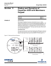
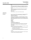
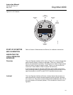
Keypad
The five membrane keys on the membrane keypad are only used during
calibration to adjust the high and low gas and to initiate the calibration
sequence (Figure 5-2).
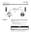
Reference Air
Ensure reference air, if used, is set to 0.25 l/min (0.5 scfh)
OPERATION
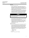
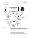
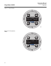
Overview Ensure the Oxymitter 4000 is at normal operation. The diagnostic LEDs will
display the operating cycle. All other LEDs should be off (Figure 5-1).
DIAGNOSTIC ALARM LEDs
If there is an error in the system, one of these LEDs will flash various blink
codes (Section 8: Troubleshooting). In the case of multiple errors, only one
will be displayed based on a priority system. Correct the problem and cycle
power. The operating display will return or the next error will be displayed. The
alarms are:
HEATER T/C
HEATER
O
2
CELL
CALIBRATION
CALIBRATION RECOMMENDED LED
Turns on when the system determines that a calibration is recommended.
Further information is available in Section 9: Maintenance and Service.
TEST POINTS
Test points 1 through 6 will allow you to monitor with a multimeter: the heater
thermocouple, O
2
cell millivolt, and the process O
2
.
1. TP1 and TP2 monitor the oxygen cell millivolt output which equates to
the percentage of oxygen present.
2. TP3 and TP4 monitor the heater thermocouple.
3. TP5 and TP6 monitor the process gas or the calibration gas parameter.
CAL LED
The CAL LED is on steady or flashing during calibration. Further information
is available in Section 9: Maintenance and Service.