


Instruction Manual
IM-106-340, Rev. 4.0
May 2006
9-7
Oxymitter 4000
OXYMITTER 4000
REPAIR
Each of the following procedures details how to remove and replace a specific
component of the Oxymitter 4000.
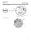
Removal and
Replacement of Probe
1. Remove.
a. Turn off power to the system.
b. Shut off the calibration gases at the cylinders and the instrument air.
c. Disconnect the calibration gas and instrument air lines from the
Oxymitter 4000.
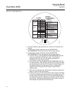
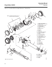
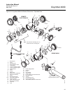
d. Remove left housing cover (27, Figure 9-3 or Figure 9-4).
e. Remove all signal and power wiring to the probe.
f. Remove insulation to access the mounting bolts.
g. Unbolt the Oxymitter 4000 from the stack and take it to a clean work
area.
h. Allow the unit to cool to a comfortable working temperature.
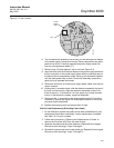
2. Replace.
a. Bolt the Oxymitter 4000 to the stack and install the insulation.
b. Connect all signal and power leads at the probe. Refer to Section 2:
Installation, for detailed wiring instructions.
c. Connect the calibration gas and instrument air lines to probe.
d. Instal left housing cover (27, Figure 9-3 or Figure 9-4).
e. Turn on instrument air.
f. Restore power to the system; refer to "Power Up" in Section 5:
Startup and Operation of Oxymitter 4000 with Membrane Keypad or
"Power Up" in Section 6: Startup and Operation of Oxymitter 4000
with LOI. When the probe is at operating temperature, calibrate the
probe per "Calibration with Keypad".
NOTE
Recalibration is required whenever electronic cards or sensing cell is
replaced.
It is recommended that the Oxymitter 4000 be removed from the stack for all service
activities. The unit should be allowed to cool and be taken to a clean work area. Failure to
comply may cause severe burns.
Disconnect and lock out power before working on any electrical components. There is
voltage up to 115 VAC.