


8-8
Instruction Manual
IM-106-340, Rev. 4.0
May 2006
Oxymitter 4000
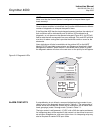
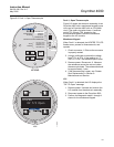
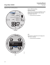
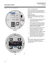
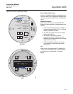
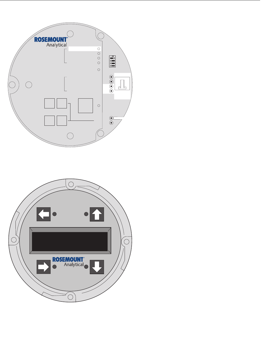
Figure 8-4. Fault 2, Shorted Thermocouple
Fault 2, Shorted Thermocouple
Figure 8-4 shows the electronic assembly for an
Oxymitter 4000 with a membrane keypad (upper
view) and an Oxymitter 4000 with an LOI (lower
view). The upper view also shows J1 and test
points TP1 through TP6, located on the
microprocessor board, below the membrane
keypad or the LOI module.
Membrane Keypad
When Fault 2 is detected, the HEATER T/C LED
flashes twice, pauses for three seconds, and
repeats.
1. Using a multimeter, measure the voltage
from TP3+ to TP4-. If the reading is 0 ±0.5
mV, then a shorted thermocouple is likely.
2. Remove power and disconnect J1.
3. Measure the resistance from TP3+ to TP4-.
The reading should be approximately 20K
ohms.
4. If so, the short is not on the PC board. The
thermocouple wiring or the thermocouple is
shorted. See "Heater Strut Replacement" in
Section 9: Maintenance and Service.
LOI
When Fault 2 is detected, the LOI displays the
"O2 T/C Shorted" message.
1. Remove power. Unscrew and remove the
LOI module from the electronic assembly.
2. Reconnect power to the Oxymitter 4000.
3. Perform the diagnostic steps 1 through 4
shown for the membrane keypad.
37260020
LOI
KEYPAD
Alarms
O2 T/C Shorted
DIAGNOSTIC
ALARMS
TEST
POINTS
HEATER T/C
HEATER
O2 CELL
CALIBRATION
CALIBRATION RECOMMENDED
O2 CELL mV +
O2 CELL mv -
HEATER T/C +
HEATER T/C -
INC INC
DEC DEC
HIGH
GAS
LOW
GAS
CAL
TEST GAS +
PROCESS -
% O2
SW2
TP1
J1
TP2
TP3
RED
YEL
GRN
ORG
TP4
TP5
TP6
ON