


Oxymitter 4000
8-4
Instruction Manual
IM-106-340, Rev. 4.0
May 2006
NOTE
Make sure that the Control System is configured to interpret these signal
levels correctly!
Once an alarm condition is indentified, the Oxymitter 4000 electronics offers a
number of diagnostics to interpret the specific alarm.
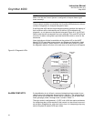
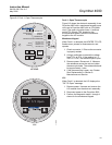
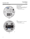
If the Oxymitter 4000 has the simple keypad operator interface, the majority of
fault conditions will be indicated by one of the four LEDs referred to as
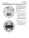
diagnostic, or unit alarms on the operator's keypad (Figure 8-2). An LED will
flash a code that will correspond to an error message. Only one LED will blink
at a time. An alarm code guide is provided inside the screw-on cover for the
electronics.
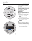
Alarm indications will also be available via the optional LOI or the HART
Model 275/375 hand-held communicator and Rosemount Analytical's Asset
Management software. When the error is corrected and/or power is cycled,
the diagnostic alarms will clear or the next error on the priority list will appear.
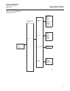
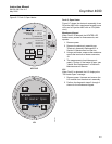
Figure 8-2. Diagnostic LEDs
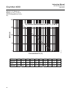
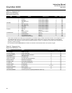
ALARM CONTACTS If autocalibration is not utilized, a common bidirectional logic contact is pro-
vided for any of the diagnostic alarms listed in Table 8-1. The assignment of
alarms which can actuate this contact can be modified to one of seven addi-
tional groupings (mode 0 through mode 7) listed in Table 7-1.
The logic contact is self-powered, +5 VDC, with a 340 ohm series resistance.
An interposing relay will be required if this contact is to be utilized to annunci-
ate a higher voltage device, such as a light or horn. An interposing relay may
also be required for certain DCS input cards.
37260044
DIAGNOSTIC
ALARMS
TEST
POINTS
HEATER T/C
HEATER
02 CELL
CALIBRATION
CALIBRATION RECOMMENDED
02 CELL mV +
02 CELL mv -
HEATER T/C +
HEATER T/C -
INC INC
DEC DEC
HIGH
GAS
LOW
GAS
CAL
TEST GAS +
PROCESS -
% 02
Diagnostic
LEDs