Instruction Manual
IB-106-340 Rev. 3.0
December 2003
7-2 HART/AMS Rosemount Analytical Inc. A Division of Emerson Process Management
Oxymitter 4000
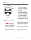
7-3 HART COMMUNICATOR PC
CONNECTIONS
There is an option to interface the HART Com-
municator with a personal computer. Load the
designated AMS software into the PC. Then link
the HART Communicator to the PC using the
interface PC adapter that connects to the serial
port (on the communicator rear panel). Refer to
the proper HART Communicator documentation
in regard to the PC interface option.
7-4 OFF-LINE AND ON-LINE OPERATIONS
The HART Communicator can be operated both
off-line and on-line.
a. Off-line operations are those in which the
communicator is not connected to the Oxy-
mitter 4000. Off-line operations can include
interfacing the HART Communicator with a
PC (refer to applicable HART documentation
regarding HART/PC applications.
b. In the on-line mode, the communicator is
connected to the 4-20 mA analog output sig-
nal line. The communicator is connected in
parallel to the Oxymitter 4000 or in parallel to
the 250 ohm load resistor.
NOTE
If the HART Communicator is turned
on while connected to the 4-20 mA
analog output signal line, an undefined
status indication appears while the
communicator warms up. Wait until the
warmup period ends to continue.
c. The opening menu displayed on the LCD is
different for on-line and off-line operations.
When powering up a disconnected (off-line)
communicator, the LCD will display the Main
Menu. When powering up a connected (on-
line) communicator, the LCD will display the
On-line Menu. Refer to the HART Communi-
cator manual for detailed menu information.
7-5 LOGIC I/O CONFIGURATIONS
The Oxymitter 4000 logic I/O output can be
configured for ten different modes through
HART/AMS. The factory default condition is
Mode 5. A list of possible configurations appear
in Table 7-1. The Unit Alarm configuration avail-
able for Modes 1, 3, 5, and 7 refers to the diag-
nostic alarm faults in Table 8-1 and Table 8-2.
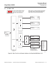
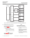
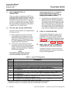
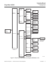
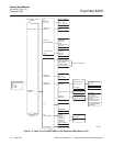
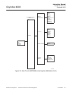
7-6 MENU TREE FOR HART COMMUNICA-
TOR/OXYMITTER 4000 APPLICATIONS
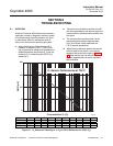
This section consists of a menu tree for the
HART Communicator. This menu is specific to
Oxymitter 4000 applications.
Table 7-1. Logic I/O Configuration
Mode Configuration
0 Unit not configured for any alarm condition.
1 Unit configured for a Unit Alarm.
2 Unit configured for Low O
2
.
3 Unit configured for both a Unit Alarm and Low O
2
.
4 Unit configured for a High AC Impedance/CALIBRATION RECOMMENDED.
5* Unit configured for both a Unit Alarm and a High AC Impedance/CALIBRATION
RECOMMENDED.
6 Unit configured for both a Low O
2
and High AC Impedance/CALIBRATION RECOMMENDED.
7 Unit configured for a Unit Alarm, a Low O
2
, and a High AC Impedance/CALIBRATION
RECOMMENDED.
8** Unit configured for a calibration handshake with IMPS 4000 or SPS 4000. CALIBRATION
RECOMMENDED will initiate the calibration cycle.
9 Unit configured for a calibration handshake. CALIBRATION RECOMMENDED will not initiate
the calibration cycle with the IMPS 4000 or SPS 4000.
*The default condition for an Oxymitter 4000 without an IMPS 4000 or SPS 4000.
**The default condition for an Oxymitter 4000 with an IMPS 4000 or SPS 4000.


