


Instruction Manual
IB-106-340 Rev. 3.0
December 2003
Rosemount Analytical Inc. A Division of Emerson Process Management Troubleshooting 8-1
Oxymitter 4000
SECTION 8
TROUBLESHOOTING
8-1 OVERVIEW
While the Oxymitter 4000 electronics provides a
significant number of diagnostic alarms to assist
in troubleshooting potential problems, it’s good
to place these alarms in perspective with re-
spect to the instrument’s operating principles:
a. When the Zirconium Oxide sensing cell is
heated to its setpoint [1357°F (736°C)], the
cell will generate a voltage that represents the
difference between the process O
2
% and the
reference O
2
% inside the probe (20.95% O
2
ambient air).
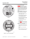
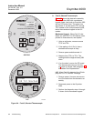
b. Test points are provided to read the raw milli-
volt value generated by the thermocouple that
controls both the cell temperature and the raw
cell signal.
c. The cell temperature at test points 3 and 4
should always be stable at approximately
29 to 30 millivolts, which represents the
736°C setpoint temperature.
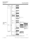
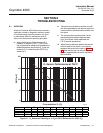
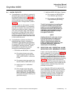
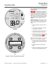
d. When flowing calibration gasses, the raw cell
millivolt value at test points 1 and 2 should
represent the levels on the chart in Figure
8-1. Note that the raw cell millivolt value in-
creases logarithmically as the O
2
concentra-
tion decreases.
37260043
1001010.01 0.10
0
50
100
150
200
Concentration O (%)
2
EMF (mV)
O Sensor Performance at 736 C
2
O
O
2
%
100201510987654
EMF(mV)
-34 1.0 7.25 16.1 18.4 21.1 23.8 27.2 31.2 36.0
O
2
%
3 2 1 0.8 0.6 0.5 0.4 0.2 0.1 0.01
EMF(mV)
42.3 51.1 66.1 71.0 77.5 81.5 86.3 101.4 116.6 166.8
Figure 8-1. O
2
Sensor mV Reading vs. % O
2
at 736ºC (Reference Air, 20.9% O
2
)