


Instruction Manual
IB-106-340 Rev. 3.0
December 2003
6-6 Setup and Operation with LOI Rosemount Analytical Inc. A Division of Emerson Process Management
Oxymitter 4000
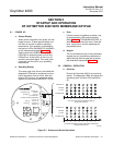
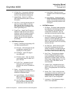
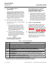
d. SYSTEM/Status
1. Alarms – Diagnostic alarms. See
Section 8, TROUBLESHOOTING.
2. PID Parameter – Displays the line volt-
age powering the Oxymitter, and infers
the temperature control algorithm being
used to control heater temperature.
3. Reset Device – Device can be reset
here as opposed to repowering. Cali-
bration parameters will be lost.
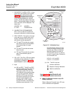
e. SYSTEM/Software
This is data regarding the Oxymitter 4000
software version, and errors that may have
occurred.
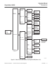
f. SENSOR DATA
Displays information about the O
2
cell and
thermocouple.
1. Temperatures
(a) O2 Temp – Indicates the thermo-
couple temperature at the sensing
cell this should always be 736° C.
(b) O2 Temp Max. – Maximum tem-
perature the cell has seen. (Some
process temperatures can exceed
the 736° C setpoint temperature,
and this will indicate this condition)
(c) Board Temp – The current tem-
perature inside the Oxymitter elec-
tronics housing (85° C is the max.)
(d) Board Temp Max. – This is the
maximum temperature that the
electronics has experienced over
time.
2. Voltages – The raw MV signals feeding
the temperature indications listed in the
previous paragraph.
3. Output Values – Indication of the cur-
rent readings for O
2
and mA.
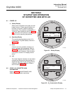
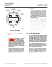
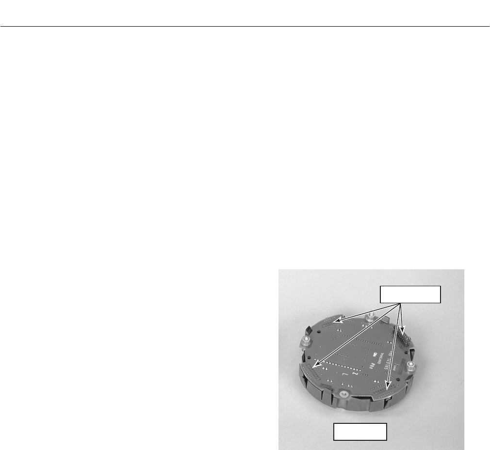
6-7 LOI INSTALLATION
The LOI module connects to the top of the elec-
tronic assembly in the electronics housing.
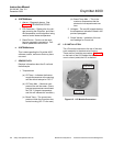
There are four matching connectors (Figure 6-5)
on the back of the LOI module that allow the
user to orient (rotate) the LOI as desired.
37260055
CONNECTOR
RECEPTACLES
LOI MODULE
REAR VIEW
Figure 6-5. LOI Module Connectors