


Instruction Manual
IB-106-340 Rev. 3.0
December 2003
2-8 Installation Rosemount Analytical Inc. A Division of Emerson Process Management
Oxymitter 4000
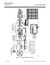
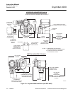
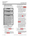
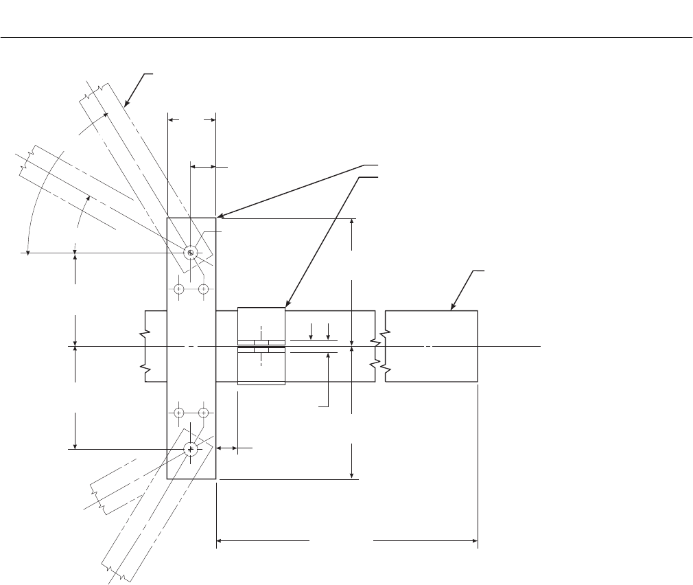
BRACE BARS
(NOT BY ROSEMOUNT)
2.00
(51)
NOTE: DIMENSIONS IN INCHES WITH
MILLIMETERS IN PARETHESES.
VERTICAL BRACE CLAMP ASSY.
ABRASIVE SHIELD
HORIZONTAL BRACE CLAMP ASSY.
(BOTH BRACE CLAMP ASSEMBLIES ARE THE SAME.
INSTALLATION AND LOCATION OF CLAMP ASSEMBLIES
AND BRACE BARS TO BE DONE IN FIELD.)
BY ROSEMOUNT
}
2 HOLES - 0.625
(16) DIA FOR
0.50 (12) DIA
BOLT
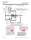
NOTE: BRACING IS FOR VERTICAL AND HORIZONTAL OXYMITTER 4000
1.00
(25) MAX
0.375
(10)
1.00
(25)
4.12
(105)
4.12
(105)
60 MAX
o
30 MIN
o
5.62
(143)
5.62
(143)
36.00 (914)
INSTALLATION. EXTERNAL BRACING REQUIRED FOR 9 FT THROUGH 18 FT
(2.75 M THROUGH 5.49 M) PROBES AS SHOWN ABOVE.
36920003
Figure 2-7. Oxymitter 4000 Abrasive Shield Bracing Installation
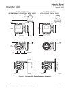
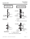
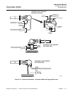
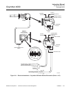
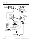
5. In vertical installations, ensure the sys-
tem cable drops vertically from the
Oxymitter 4000 and the conduit is
routed below the level of the electron-
ics housing. This drip loop minimizes
the possibility that moisture will dam-
age the electronics (Figure 2-9).
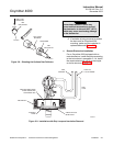
6. If the system has an abrasive shield,
check the dust seal gaskets. The joints
in the two gaskets must be staggered
180°. Also, make sure the gaskets are
in the hub grooves as the Oxymitter
4000 slides into the 15° forcing cone in
the abrasive shield.
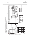
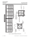
7. Insert probe through the opening in the
mounting flange and bolt the unit to the
flange. When probe lengths selected
are 9 to 18 ft (2.74 to 5.49 m), special
brackets are supplied to provide addi-
tional support for the probe inside the
flue or stack (Figure 2-7).
NOTE
If process temperatures will exceed
392°F (200°C), use anti-seize com-
pound on stud threads to ease future
removal of Oxymitter 4000. For probe
temperatures that will exceed 185°F
(85°C), we recommend the remote
mounted electronics option.