


Instruction Manual
IB-106-340 Rev. 3.0
December 2003
Rosemount Analytical Inc. A Division of Emerson Process Management Startup and Operation with LOI 6-5
Oxymitter 4000
6. O2 Next Cal – If automatic calibration
is selected, this selects the time until
the first initial calibration takes place.
7. Autocalibrate – Select if an SPS or
IMPS autocalibration system is part of
the system.
8. Gas Time – How long should each cal
gas flow. Factory default is 300 sec-
onds, but the user may want to vary
this depending upon the length of cali-
bration gas tubing runs.
9. Purge Time – Used if the O2 output is
selected to hold the last value during
calibration. After the second cal gas is
removed, how long until the sensor
comes back to the normal process
reading, and the 4-20 mA signal can
be released.
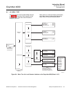
b. SYSTEM/Input/Output
1. Analog – Pertaining to the analog 4-20
mA signal representing O2
(a) O2 Type – 4-20 mA signal may be
configured to increase with in-
creasing O2 or the reverse.
(b) O2 Range – upper O2 range is
user selectable.
(c) O2 Alarm Level – User can config-
ure the digital output to alarm at a
given O2 level.
(d) Do O2 Trim – procedure for cali-
brating the 4-20 mA signal to a
precision mA source. Procedure is
intuitive.
2. Digital – A bi-directional logic signal
may be configured as an alarm, or as a
calibration handshake signal.
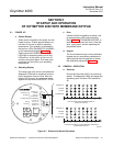
(a) Logic I/O Mode – One of 9 different
sets of conditions can be set for the
digital signal . See Table 4-1.
(b) Low O2 Alarm – If any of the condi-
tions noted above include a low O2
process alarm, set the value here.
(c) Input State – Notes the current
condition of the bi-directional digital
signal.
(d) Force Output – Forces the output
state of the signal to either open or
closed. This is used primarily when
diagnosing potential problems with
this signal.
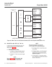
c. SYSTEM/Parameters
1. O2 Slope – O2 slope is data regarding
the strength of the sensing cell output.
This information is automatically cal-
culated after a calibration, and the
user does not normally input this data.
2. O2 Constant – O2 constant is the
amount of voltage a cell generates with
ambient air as the calibration gas.
Again, this is normally calculated as a
result of calibration, and in not normally
input by the user.
3. O2 T90 Time – Some users may feel
that the O2 reading is too active for
certain processes. The feature permits
the user to dampen the O2 signal. De-
fault value is zero seconds dampening.
4. Auto Tune – The electronics detects
the line voltage powering the instru-
ment automatically, and picks proper
algorithms for heater control. User can
force a high voltage algorithm, or a low,
but Auto Tune is the default, and is
recommended.
5. Lockout Time – Keypad lockout time
default is 30 sec., but is user configur-
able. A Z keypad pattern will unlock the
keypad.
6. Revert Time – Once a user goes one
level deep into the menu structure, and
additional time is provided to prevent
nuisance lockouts. One hour is the
default, and it is user configurable
7. Luminance – Gas florescence bright-
ness is user adjustable.