


Instruction Manual
IB-106-340 Rev. 3.0
December 2003
9-14 Maintenance and Service Rosemount Analytical Inc. A Division of Emerson Process Management
Oxymitter 4000
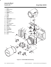
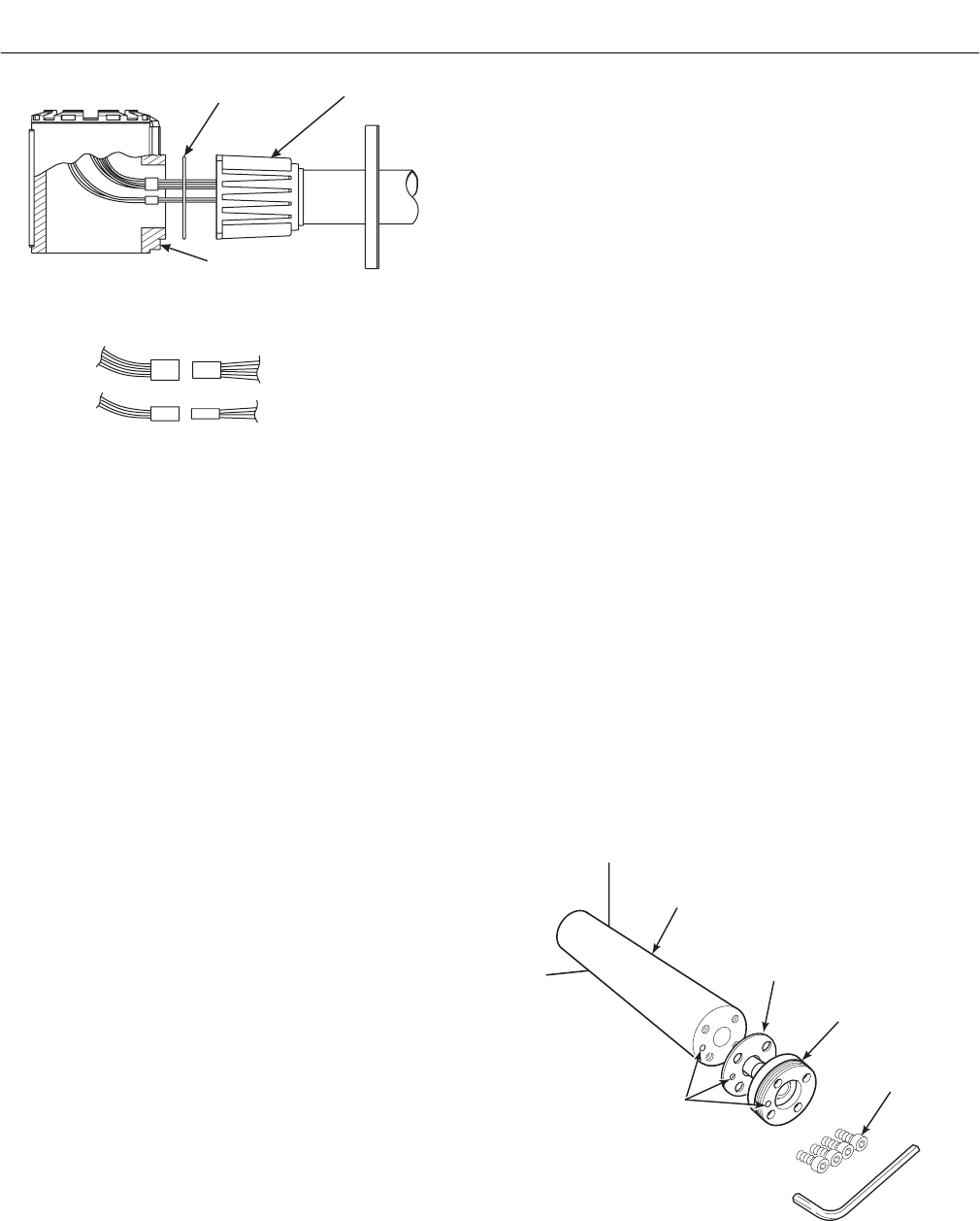
SIGNAL
CABLE
(9)
HEATER
CABLE
(8)
PROBE SIGNAL
WIRE CONNECTOR
PROBE HEATER
WIRE CONNECTOR
4 WIRE
2 WIRE
HOUSING (21)
O-RING (10)
PROBE (6)
37260058
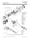
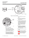
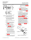
Figure 9-9. Probe to Probe Head Assembly –
Remote Electronics Only
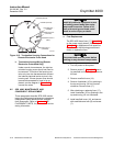
10. Push down on the back plate of the
strut to make sure you have spring
tension and then tighten the three
screws on the back plate.
11. Replace the CAL and REF gas silicon
tubes.
12. For units with integral electronics, in-
stall the entire electronics per para-
graph 9-4c, steps 7 through 13.
13. For units with remote electronics,
install the probe head as follows:
(a) See Figure 9-9. Make sure that the
O-ring (10) is in good condition.
Seat the O-ring in the mating
groove of the probe (6).
(b) Insert the probe signal cables
(8 and 9, into the housing (21).
(c) Turn the conduit ports of the
housing (21) to the CAL and REF
gas ports side of the probe (6) and
position the housing on the probe
(d) Install and tighten four screws (12,
Figure 9-4).
(e) Reconnect the probe signal cables
(8 and 9) to the probe signal and
heater wire connectors, Figure 9-9.
Make sure the connectors are se-
cure.
(f) Install and tighten cover.
14. Follow the instructions in paragraph
9-4a.2 to install the Oxymitter 4000 into
the stack or duct. If installing an Oxy-
mitter 4000/SPS 4000 assembly, follow
the instructions in paragraph 9-4b.2.
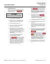
i. Cell Replacement
This paragraph covers oxygen sensing cell
replacement. Do not attempt to replace the
cell until all other possibilities for poor per-
formance have been considered. If cell re-
placement is needed, order the cell
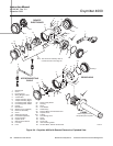
replacement kit (Table 11-1). Refer to
Figure 9-3 or Figure 9-4 to view the compo-
nent parts of the Oxymitter 4000.
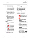
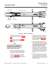
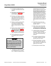
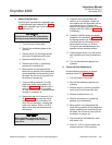
The cell replacement kit (Figure 9-10) con-
tains a cell and flange assembly, corrugated
seal, setscrews, socket head cap screws,
and anti-seize compound. The items are
carefully packaged to preserve precise
surface finishes. Do not remove items from
the packaging until they are ready to be
used. Spanner wrenches and hex wrenches
needed for this procedure are part of an
available special tools kit (Table 11-1 and
Figure 11-2).
PROBE TUBE
(NOT INCLUDED
IN KIT)
SOCKET HEAD
CAP SCREWS
CORRUGATED
SEAL
CELL AND
FLANGE
ASSEMBLY
CALIBRATION GAS
PASSAGE
22220028
Figure 9-10. Cell Replacement Kit