


Instruction Manual
IB-106-340 Rev. 3.0
December 2003
Rosemount Analytical Inc. A Division of Emerson Process Management Maintenance and Service 9-9
Oxymitter 4000
(f) On the terminal strip, loosen the
screws securing the customer-
wired LINE IN and NEUTRAL
leads to terminals L and N. Also,
remove the customer-wired ground
lead from the ground lug. Remove
the leads from the terminal strip
and slide them from the manifold
through the line voltage conduit
port.
(g) Next, loosen the screws of remote
contact input terminals 1 and 2; 4-
20 mA terminals 3 and 4; and relay
output terminals 7, 8, 9, and 10.
Remove the leads from the termi-
nal strip and slide them from the
manifold through the signal conduit
port.
(h) Remove insulation to access the
mounting bolts. Unbolt the Oxy-
mitter 4000/SPS 4000 assembly
from the stack and take the entire
assembly to a clean work area.
(i) Allow the unit to cool to a comfort-
able working temperature.
2. Replace.
(a) Bolt the Oxymitter 4000/SPS 4000
assembly to the stack and install
insulation.
(b) Follow the instructions in para-
graph 2-4 to connect the line volt-
age and signal leads to an Oxy-
mitter 4000/ SPS 4000 assembly.
(c) Follow the instructions in para-
graph 2-6 to connect the calibra-
tion gases and instrument air to an
Oxymitter 4000/SPS 4000 assem-
bly. Turn on the calibration gases
at the cylinders and turn on instru-
ment air.
(d) Restore power to the system.
c. Replace Entire Integral Electronics (with
Housing)
NOTE
Only perform this procedure on units
with integral electronics and without
integrally-mounted SPS 4000 units. If it
is necessary to replace the entire elec-
tronics on an Oxymitter 4000/ SPS
4000 assembly, contact Rosemount
for further instructions.
NOTE
Recalibration is required whenever
electronic cards or sensing cell is re-
placed.
1. Follow the instructions in paragraph
9-4a.1 to remove the Oxymitter 4000
from the stack or duct. If removing an
Oxymitter 4000/SPS 4000 assembly,
follow the instructions in paragraph
9-4b.1.
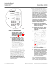
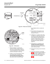
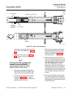
2. Remove the right housing cover un-
covering the electronic assembly
(Figure 9-5).
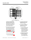
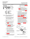
3. Depress and remove the J1 (cell and
T/C) connector from the J1 socket.
Loosen the three captive mounting
screws on the microprocessor board
(top board).
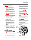
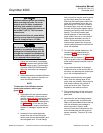
4. The J8 connector (heater leads) can be
accessed by moving the J1 connector
leads out of the slot on the microproc-
essor board and sliding the electronic
assembly partially out of the housing
(Figure 9-6).
5. Squeeze the J8 connector on the sides
and carefully remove. The electronic
assembly can now be completely re-
moved from the housing.
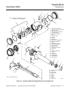
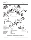
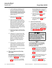
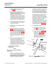
6. Remove the four screws (7, Figure 9-3)
from the probe finned housing. The
probe and the electronic housing can
now be separated.