


Instruction Manual
IB-106-340 Rev. 3.0
December 2003
Rosemount Analytical Inc. A Division of Emerson Process Management Troubleshooting 8-7
Oxymitter 4000
DIAGNOSTIC
ALARMS
TEST
POINTS
HEATER T/C
HEATER
O2 CELL
CALIBRATION
CALIBRATION RECOMMENDED
O2 CELL mV +
O2 CELL mv -
HEATER T/C +
HEATER T/C -
INC INC
DEC DEC
HIGH
GAS
LOW
GAS
CAL
TEST GAS +
PROCESS -
% O2
SW2
TP1
J1
TP2
TP3
RED
YEL
GRN
ORG
TP4
TP5
TP6
ON
37260021
Alarms
O2 T/C Reversed
LOI
KEYPAD
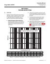
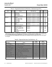
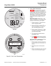
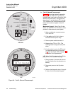
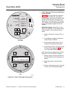
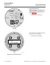
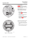
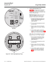
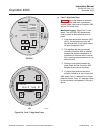
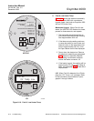
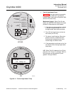
Figure 8-5. Fault 3, Reversed Thermocouple
c. Fault 3, Reversed Thermocouple Wiring or
Faulty PC Board
Figure 8-5 shows the electronic assembly
for an Oxymitter 4000 with a membrane
keypad (upper view) and an Oxymitter 4000
with an LOI (lower view). The upper view
also shows J1 and test points TP1 through
TP6, located on the microprocessor board,
below the membrane keypad or the LOI
module.
Membrane Keypad. When Fault 3 is de-
tected, the HEATER T/C LED flashes three
times, pauses for three seconds, and re-
peats.
1. Using a multimeter, measure TP3+ to
TP4-.
2. If the reading is negative, the thermo-
couple wiring is reversed.
3. Check red and yellow wires in the J1
connector for the proper placement.
4. If the wiring is correct, the fault is in the
PC board. See paragraph 9-4d, Elec-
tronic Assembly Replacement.
LOI. When Fault 3 is detected, the LOI dis-
plays the “O2 T/C Reversed” message.
1. Remove power. Unscrew and remove
the LOI module from the electronic as-
sembly.
2. Reconnect power to the Oxymitter
4000.
3. Perform the diagnostic steps 1 through
4 shown for the membrane keypad.