


Instruction Manual
IB-106-340 Rev. 3.0
December 2003
iv Rosemount Analytical Inc. A Division of Emerson Process Management
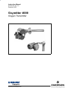
Oxymitter 4000
Figure 8-8. Fault 6, High High Heater Temp.......................................................................... 8-10
Figure 8-9. Fault 7, High Case Temp..................................................................................... 8-11
Figure 8-10. Fault 8, Low Heater Temp ................................................................................... 8-12
Figure 8-11. Fault 9, High Heater Temp .................................................................................. 8-13
Figure 8-12. Fault 10, High Cell mV......................................................................................... 8-14
Figure 8-13. Fault 11, Bad Cell ................................................................................................8-15
Figure 8-14. Fault 12, EEPROM Corrupt ................................................................................. 8-16
Figure 8-15. Fault 13, Invalid Slope ......................................................................................... 8-17
Figure 8-16. Fault 14, Invalid Constant .................................................................................... 8-18
Figure 8-17. Fault 15, Last Calibration Failed.......................................................................... 8-19
Figure 8-18. Probe Leakage Paths .......................................................................................... 8-20
Figure 8-19. SPS 4000 Troubleshooting Flowchart................................................................. 8-23
Figure 9-1. Membrane Keypad................................................................................................. 9-2
Figure 9-2. Inside Right Cover .................................................................................................9-3
Figure 9-3. Oxymitter 4000 with Integral Electronics, Exploded View ..................................... 9-7
Figure 9-4. Oxymitter 4000 with Remote Electronics, Exploded View..................................... 9-8
Figure 9-5. Electronic Assembly............................................................................................. 9-10
Figure 9-6. J8 Connector........................................................................................................ 9-10
Figure 9-7. Fuse Location ......................................................................................................9-11
Figure 9-8. Heater Strut Assembly......................................................................................... 9-13
Figure 9-9. Probe to Probe Head Assembly – Remote Electronics Only............................... 9-14
Figure 9-10. Cell Replacement Kit ........................................................................................... 9-14
Figure 9-11. Ceramic Diffusion Element Replacement............................................................ 9-16
Figure 9-12. Termination Housing Connections for Remote Electronics Probe Head............. 9-18
Figure 9-13. SPS 4000 Manifold Assembly ............................................................................. 9-20
Figure 9-14. Power Supply Board and Interface Board Connections ...................................... 9-22
Figure 9-15. Calibration Gas and Reference Air Components ................................................ 9-25
Figure 11-1. Cell Replacement Kit ........................................................................................... 11-3
Figure 11-2. Probe Disassembly Kit......................................................................................... 11-5
LIST OF TABLES
Table 1-1. Product Matrix ......................................................................................................1-16
Table 1-2. Calibration Components ...................................................................................... 1-17
Table 1-3. Intelligent Multiprobe Test Gas Sequencer Versions ............................................ 1-18
Table 3-1. Logic I/O Configuration (as set at HART/AMS or LOI) .......................................... 3-4
Table 4-1. Logic I/O Configuration (as set at HART/AMS or LOI) .......................................... 4-4
Table 7-1. Logic I/O Configuration.......................................................................................... 7-2
Table 8-1. Diagnostic/Unit Alarm Fault Definitions – Membrane Keypad Only ...................... 8-4
Table 8-2. Diagnostic/Unit Alarm Fault Definitions – LOI ....................................................... 8-4
Table 8-3. SPS 4000 Fault Finding....................................................................................... 8-22
Table 11-1. Replacement Parts for Probe .............................................................................. 11-1
Table 11-2. Replacement Parts for Electronics ...................................................................... 11-6
Table 11-3. Replacement Parts for SPS 4000......................................................................... 11-7
Table 11-4. Replacement Parts for Calibration Components ................................................. 11-7