


Instruction Manual
IB-106-340 Rev. 3.0
December 2003
9-24 Maintenance and Service Rosemount Analytical Inc. A Division of Emerson Process Management
Oxymitter 4000
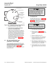
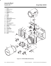
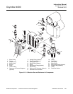
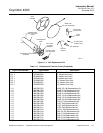
h. Flowmeter Replacement
Use this procedure to replace either refer-
ence air flowmeter (16, Figure 9-15) or cali-
bration gas flowmeter (17).
1. Turn off power to the system.
2. Shut off the calibration gases at the
cylinders.
3. Loosen, but do not remove, four
screws (13) securing flowmeter bracket
(25) to the manifold.
4. Flex the bottom of flowmeter bracket
(25) downward and away to disengage
and remove from the manifold.
5. For reference air flowmeter (16), re-
move pressure regulator (8) by discon-
necting tubing (11) from elbow fitting
(10). Also, disconnect tubing (24) from
straight fitting (23).
For calibration gas flowmeter (17), dis-
connect tubing (18) at elbow fitting
(21). Also, disconnect gas tubing (2)
from elbow fitting (15).
6. Remove screws (6) and bracket (5) se-
curing flowmeter (16 or 17) to flowme-
ter bracket (25).
7. Remove flowmeter (16 or 17), with in-
stalled fittings, from flowmeter bracket
(25).
8. For reference air flowmeter (16), re-
move elbow street fittings (14 and 22).
It is not necessary to remove fittings
(10 and 23) from the street fittings.
For calibration gas flowmeter (17), re-
move elbow fittings (15 and 21).
9. Apply pipe thread sealant to the
threads of top fittings (22 or 21) and
bottom fittings (14 or 15) and install fit-
tings into new flowmeter (16 or 17).
10. Position flowmeter (16 or 17) into
flowmeter bracket (25) and secure with
bracket (5) and screw (6).
11. For reference air flowmeter (16), con-
nect tubing (11) to elbow fitting (10)
and install pressure regulator (9). Also,
connect tubing (24) to straight fitting
(23).
For calibration gas flowmeter (17),
connect tubing (2) to elbow fitting (15)
and connect tubing (18) to elbow fitting
(21).
12. Slide the top slots of flowmeter bracket
(25) onto screws (13). Flex the bottom
of the bracket downward and toward
the manifold to engage the bottom
bracket slots and screws. Tighten
screws.
13. Turn on the calibration gases at the
cylinders.