


Instruction Manual
IB-106-340 Rev. 3.0
December 2003
Rosemount Analytical Inc. A Division of Emerson Process Management Startup and Operation with Keypad 5-1
Oxymitter 4000
SECTION 5
STARTUP AND OPERATION
OF OXYMITTER 4000 WITH MEMBRANE KEYPAD
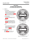
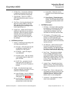
5-1 POWER UP
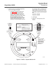
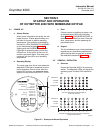
a. Startup Display
When power is applied to the probe, the cell
heater turns on. It takes approximately one
half hour for the cell to heat to operating
temperature. This condition is indicated by
the top four LEDs (DIAGNOSTIC ALARMS)
on the membrane keypad (Figure 5-1).
Starting with the CALIBRATION LED, the
LEDs light in ascending order until all four
LEDs are on. At this point, all four turn off
and the cycle starts again. This ramp cycle
continues until the cell is up to operating
temperature.
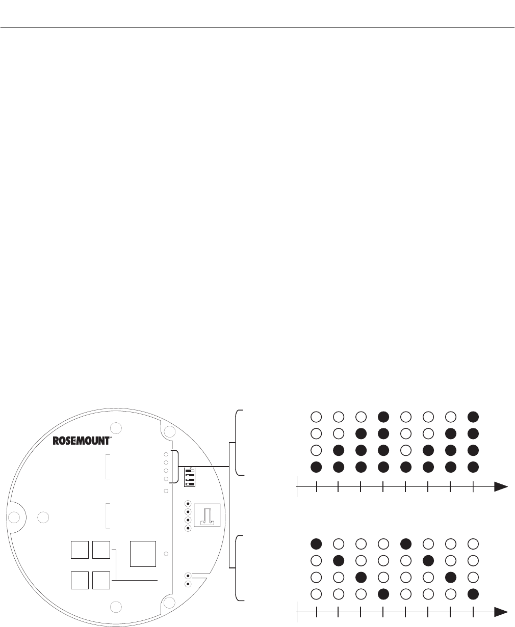
b. Operating Display
The ramp cycle turns into a cycle where the
diagnostic LEDs light in sequence from the
top to the bottom, one at a time. After the
bottom LED turns on, the sequence starts
again at the top with the HEATER T/C LED.
c. Error
If there is an error condition at startup, one
of the diagnostics LEDs will be blinking.
Refer Section 7, TROUBLESHOOTING, to
determine the cause of the error. Clear the
error, cycle power, and the operating dis-
play should return.
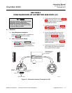
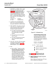
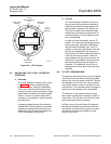
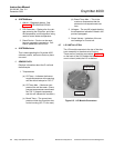
d. Keypad
The five membrane keys on the membrane
keypad are only used during calibration to
adjust the high and low gas and to initiate
the calibration sequence (Figure 5-2).
5-2 GENERAL OPERATION
a. Overview
Ensure the Oxymitter 4000 is at normal op-
eration. The diagnostic LEDs will display the
operating cycle. All other LEDs should be
off.
DIAGNOSTIC
ALARMS
TEST
POINTS
HEATERT/C
HEATER
O2 CELL
CALIBRATION
CALIBRATION RECOMMENDED
O2 CELL mV +
O2 CELL mv -
HEATERT/C +
HEATERT/C -
INC INC
DEC DEC
HIGH
GAS
LOW
GAS
CAL
TEST GAS +
PROCESS -
% O2
SW2
TP1
J1
TP2
TP3
RED
YEL
GRN
ORG
TP4
TP5
TP6
ON
HEATER T/C
HEATER
O CELL
2
CALIBRATION
LIGHTING SEQUENCE DURING NORMAL OPERATION
(OPERATING DISPLAY)
1
2 3 4 1 2 3 4
HEATER T/C
HEATER
O CELL
2
CALIBRATION
LIGHTING SEQUENCE DURING WARM-UP
(STARTUP DISPLAY)
1
2 3 4 1 2 3 4
22220056
Figure 5-1. Startup and Normal Operation