Instruction Manual
IB-106-340 Rev. 3.0
December 2003
Rosemount Analytical Inc. A Division of Emerson Process Management P-25
Oxymitter 4000
QUICK START GUIDE
FOR OXYMITTER 4000 SYSTEMS
Before using the Quick Start Guide, please read “WHAT YOU NEED TO KNOW BEFORE
INSTALLING AND WIRING A ROSEMOUNT OXYMITTER 4000 OXYGEN TRANSMIT-
TER” on the preceding page.
1. Install the Oxymitter 4000 in an appropriate location on the stack or duct. Refer to Section 2,
paragraph 2-1.a for information on selecting a location for the Oxymitter 4000.
2. If using an SPS 4000, connect the calibration gasses to the appropriate fittings on the SPS
4000 manifold.
3. Connect reference air to the Oxymitter 4000 or SPS 4000, as applicable.
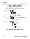
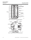
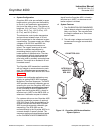
4. If using an SPS 4000, make the following wire connections as shown in Figure 3: line volt-
age, cal initiate-remote contact input, relay output, and 4-20 mA.
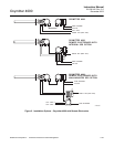
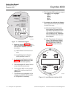
5. If NOT using an SPS 4000, make the following wire connections as shown in Figure 4: line
voltage, 4-20 mA, and logic I/O.
6. Verify the Oxymitter 4000 switch configuration is as desired. Refer to Section 3, paragraphs
3-1.c, 3-1.d, and 3-1.e, or Section 4, paragraphs 4-1.c, 4-1.d, and 4-1.e.
7. Apply power to the Oxymitter 4000; the cell heater will turn on. Allow approximately one half
hour for the cell to heat to operating temperature. Once the ramp cycle has completed and
the Oxymitter 4000 is at normal operation, proceed with step 8 or 9.
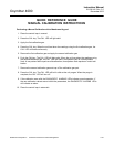
8. If using an SPS 4000, initiate a semi-automatic calibration.
9. If NOT using an SPS 4000, perform a manual calibration. Refer to Section 9, paragraph 9-2
or paragraph 9-3, in this instruction bulletin.
NOTE
If your system has a membrane keypad you can refer to the Quick Start Guide on the follow-
ing pages.


