


Instruction Manual
IB-106-340 Rev. 3.0
December 2003
Rosemount Analytical Inc. A Division of Emerson Process Management Configuration with LOI 4-1
Oxymitter 4000
SECTION 4
CONFIGURATION OF OXYMITTER 4000 WITH LOI
Install all protective equipment covers
and safety ground leads before
equipment startup. Failure to install
covers and ground leads could result
in serious injury or death.
4-1 GENERAL
a. Verify Mechanical Installation
Ensure the Oxymitter 4000 is installed cor-
rectly (Section 2, INSTALLATION).
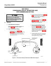
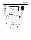
b. Verify Terminal Block Wiring
1. Remove screw (32, Figure 9-3 or
Figure 9-4), gasket (33), and cover lock
(34) that secure the housing cover
(27). Remove the cover to expose the
terminal block (25).
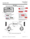
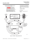
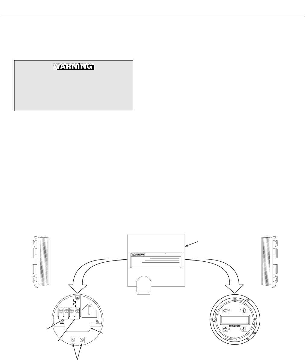
2. Check the terminal block wiring, Figure
4-1. Be sure the power, 4-20 mA sig-
nal, and logic outputs are properly
connected and secure.
3. Install the housing cover (27, Figure
9-3 or Figure 9-4) on the terminal block
and secure with cover lock (34), gasket
(33), and screw (32).
4. For an Oxymitter 4000 with an inte-
grally mounted SPS 4000, remove
screws (26, Figure 9-13) and terminal
cover (27). Check that the power and
signal terminations are properly con-
nected to terminal strip (25) and secure
according to instructions in Section 2,
INSTALLATION.
5. Install terminal cover (27) and secure
with screws (26). Make sure terminal
cover gasket (28) is in place.
AC L1
AC N
+
+
-
-
4-20
500 VA
SERIAL NO.
TAG NO.
OXYMITTER 4000
WATTS:VOLTS:
FUSE:LINE
OUTPUT:
Rosemount Analytical Inc.
Orrville, OH 44667-0901
85-264 VAC 48-62 Hz
TM
800-433-6076
4-20 mA
R
5 Amps
TM
HART
SMART FAMILY
4-20 mA
SIGNAL
LOGIC I/O
GROUND LUGS
TERMINAL
BLOCK
OXYMITTER 4000
ELECTRONICS
HOUSING
37260011
LOI
Figure 4-1. Electronics Housing Terminals and LOI