


Instruction Manual
IB-106-340 Rev. 3.0
December 2003
Rosemount Analytical Inc. A Division of Emerson Process Management Maintenance and Service 9-21
Oxymitter 4000
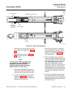
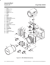
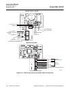
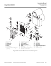
c. Solenoid Replacement
The SPS 4000 manifold has a calibration gas
1 (high calibration gas) solenoid (20, Figure
9-13) and a calibration gas 2 (low calibration
gas) solenoid (13).
Disconnect and lock out power before
working on any electrical components.
1. Turn off power to the system.
2. Shut off the calibration gases at the
cylinders.
3. Remove screw (7) securing manifold
cover lock (6) and remove the lock.
4. Remove manifold cover (14).
5. Remove two screws (11) attaching
spacers (9) to manifold (5).
6. Being careful not to disconnect the
board wiring, carefully lift the board and
spacer assembly from manifold (5) and
set aside. Do not lose O-rings (8) from
the bottom of spacers (9).
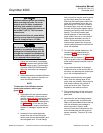
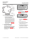
7. Tag and unplug solenoid (13 or 20)
leads from power supply board (18).
Refer to Figure 9-14. Calibration gas 1
solenoid wires connect to connector
J5, and calibration gas 2 solenoid wires
connect to connector J4.
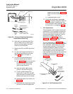
8. Remove the top nut of solenoid (13 or
20, Figure 9-13) securing the coil as-
sembly and washer to the base. Re-
move the coil assembly, including the
leads, and washer. Place a 13/16 in.
deep socket over the solenoid base
and remove.
When installing a solenoid, do not
over-tighten. Damage to the solenoid
may occur.
9. Install the new solenoid base. Be
careful not to overtighten. Install the
new washer and coil assembly and se-
cure with the top nut. Connect the
leads to the proper connector on power
supply board (18). Refer to Figure 9-14
if necessary.
10. Carefully install the board and spacer
assembly into manifold (5, Figure 9-13)
by aligning spacers (9) with the
mounting holes on the manifold and
securing with screws (11). Ensure
O-rings (8) are installed between the
spacers and the manifold surface.
11. Install manifold cover (14), and secure
with manifold cover lock (6) and screw
(7).
12. Turn on the calibration gases at the
cylinders.
d. Pressure Switch Replacement
Use the following procedure to replace
pressure switch (12, Figure 9-13).
1. Turn off power to the system.
2. Shut off the calibration gases at the
cylinders.
3. Remove screw (7) securing manifold
cover lock (6) and remove the lock.
4. Remove manifold cover (14).
5. Remove two screws (11) attaching
spacers (9) to manifold (5).
6. Being careful not to disconnect the
board wiring, carefully lift the board and
spacer assembly from manifold (5) and
set aside. Do not lose O-rings (8) from
the bottom of spacers (9).
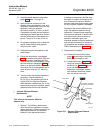
7. Tag and remove the leads from pres-
sure switch (12).
8. Place a 1-1/16 in. 6-point socket over
pressure switch (12) and remove.