


Instruction Manual
IB-106-340 Rev. 3.0
December 2003
Rosemount Analytical Inc. A Division of Emerson Process Management Configuration with LOI 4-3
Oxymitter 4000
f. Once the cell is up to operating temperature,
the O
2
percentage can be read:
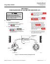
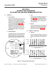
1. To access TP5 and TP6 next to the
LOI (Figure 4-2), power down the
Oxymitter 4000 and remove the LOI
module. Attach alligator leads from a
multimeter across TP5 and TP6. Install
the LOI module and power up the
Oxymitter 4000. Allow time for the cell
to reach operating temperature. The
calibration and process gases can now
be monitored. When a calibration has
been initiated, the value at TP5 and
TP6 is the % O
2
seen by the cell. Oxy-
gen levels, as seen on the multimeter,
are:
8.0% O2 = 8.0 VDC
0.4% O2 = 0.4 VDC
2. HART/AMS.
3. Model 751. The loop-driven LCD
display.
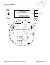
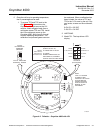
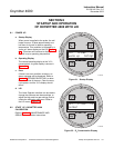
SW2
SW1
1
2
3
4
TP1
J1
TP2
TP3
RED
YEL
GRN
ORG
TP4
TP5
TP6
4-20 mA
IS INTERNALLY
POWERED
(DEFAULT)
4-20 mA REQUIRES
EXTERNAL POWER
HART
0 TO 10% O
2
3.5 mA
220 V 115 V
0 TO 25% O
2
LOCAL
21.6 mA
DEFAULT
POSITION
(EX-FACTORY)
3.5 mA/21.6 mA:
0 TO 25% O :
2
0 TO 10% O /
2
LOCAL:
HART:
O RANGE SET BY HART/AMS
(FROM 0 TO 40% O )
O RANGE SET BY POS 2
O RANGE
WHEN ALARM EXISTS, OR
ON POWER UP, CURRENT
OUTPUT GOES TO THIS VALUE
2
2
2
2
37260012
ON
OFF
NOTE:
THE 115 V OPTION
AT SWITCH SW2
POSITION 4 IS ACTIVE
ONLY WHEN THE
HEATER VOLTAGE
OPTION IS SET TO
MANUAL IN THE
SOFTWARE.
Figure 4-2. Defaults – Oxymitter 4000 with LOI