


Instruction Manual
IB-106-340 Rev. 3.0
December 2003
2-16 Installation Rosemount Analytical Inc. A Division of Emerson Process Management
Oxymitter 4000
--
-
-
++
+
+
CAL INITIATE
CAL FAIL
LINE IN
IN CAL
NEUTRAL
GROUND
4-20 mA
CONNECTION
NOT USED
NOT USED
5 - 30 VDC TO RELAY OUTPUT
CONNECTIONS
5 VDC
(SELF-POWERED)
TO REMOTE
CONTACT INPUT
CONNECTION
90 - 250 VAC,
50/60 HZ LINE
VOLTAGE
INPUT
FACTORY
WIRING
TO INTERFACE
BOARD
FACTORY WIRING
TO INTERFACE BOARD
FACTORY WIRING
TO POWER SUPPLY
BOARD
FACTORY
WIRING TO
OXYMITTER
4000
FACTORY
WIRING TO
OXYMITTER
4000
26170027
BLACK
WHITE
BROWN
YELLOW
RED
BLUE
ORANGE
GREEN
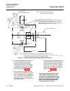
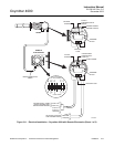
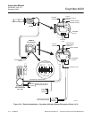
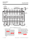
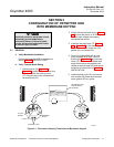
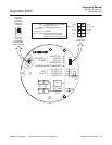
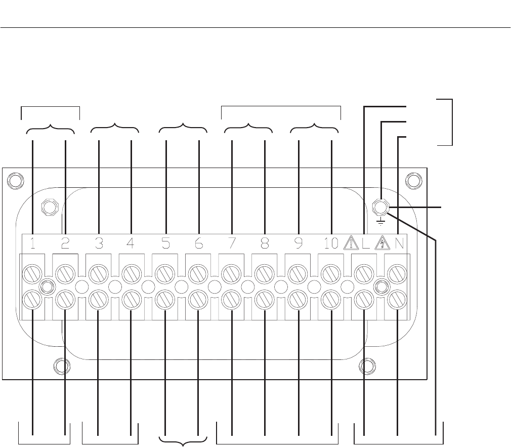
Figure 2-12. SPS 4000 Electrical Connections
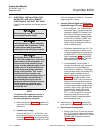
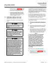
e. Connect Line Voltage
Route the line voltage leads into the mani-
fold through the 1/2 in. line voltage conduit
fitting (Figure 2-3) and out through the bot-
tom of the manifold. Connect the LINE IN
and NEUTRAL leads to terminals L and N,
respectively, as shown in Figure 2-12. Also,
be sure to connect the ground wire to the
ground lug. The unit automatically will con-
figure itself for 90 to 250 VAC line voltage
and 50/60 Hz. The power supply requires
no setup.
f. Connect Remote Contact Input Wiring
To set up the SPS 4000 to initiate a calibra-
tion from a remote location, route the 5 VDC
calibration initiate contact input leads
through the 1/2 in. NPT signal conduit port
(Figure 2-3) and out through the bottom of
the manifold. Connect the (+) and (-) CAL
INITIATE leads to terminals 1 and 2, re-
spectively, as shown in Figure 2-12.