


Instruction Manual
IB-106-340 Rev. 3.0
December 2003
Rosemount Analytical Inc. A Division of Emerson Process Management Maintenance and Service 9-19
Oxymitter 4000
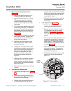
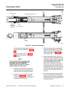
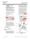
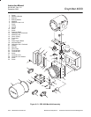
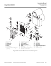
b. Board Replacement
Perform the following procedure to replace
power supply board (18, Figure 9-13) or in-
terface board (19).
Disconnect and lock out power before
working on any electrical components.
1. Turn off power to the system.
2. Remove screw (7) securing manifold
cover lock (6) and remove the lock.
3. Remove manifold cover (14).
4. Remove two screws (11) attaching
spacers (9) to manifold (5).
5. Being careful not to disconnect the
board wiring, carefully lift power supply
board (18) and interface board (19)
from manifold (5) and set aside. Do not
lose O-rings (8) from the bottom of
spacers (9).
6. Tag all leads on the board to be re-
placed to simplify installation.
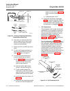
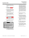
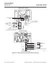
7. See Figure 9-14. If removing the power
supply board, remove line voltage input
leads from connector J7. Unplug cali-
bration gas 1 solenoid leads from con-
nector J5, calibration gas 2 solenoid
leads from connector J4, and pressure
switch leads from connector J2.
See Figure 9-14. If removing the inter-
face board, remove the CAL INITIATE
leads from connector J3, CAL FAIL
and IN CAL leads from connector J4,
and logic I/O handshake connection
from connector J5.
8. Remove stop nuts (22, Figure 9-13),
washers (21), and screws (10) secur-
ing power supply board (18) and inter-
face board (19) to spacers (9).
9. Carefully separate boards (18 and 19).
10. Connect replacement board to board
(18 or 19).
11. Install screws (10), washers (21), and
stop nuts (22) to secure power supply
board (18) and interface board (19) to
spacers (9).
12. Install all applicable leads in the appro-
priate locations on the power supply
board or interface board as shown in
Figure 9-14.
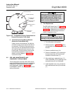
13. Install power supply board (18, Figure
9-13) and interface board (19) into
manifold (5). Align spacers (9) with the
mounting holes on the manifold and
secure with screws (11). Ensure
O-rings (8) are installed between the
spacers and the manifold surface.
14. Install manifold cover (14) and secure
with manifold cover lock (6) and screw
(7).