


Celeron™ Processor Development Kit Manual
Index-1
Index
#, defined 1-1
440BX AGPset 3-2
82371EB PCI ISA IDE Xcelerator (PIIX4E)
2-1, 3-4
82443BX Host Bridge/Controller
2-1
A
Address size 3-3
AGP connector
3-5, 4-10
AGP support 2-1, 3-2, 3-3
ATX power connector
4-3
B
Baseboard 2-1
Beep codes
5-1, 5-15
BIOS
2-7
Basic Setup Screen 5-3
configuring
2-7
Configuring floppy drives
5-4
Configuring IDE drives 5-5
console redirection
5-9
Custom Setup Screen
5-6
Drive assignments 5-4
Integrated BIOS debugger
5-10
Setup Screen System
5-2
Shadow Configuration Setup Screen 5-7
Standard Diagnostics Routines Setup Screen
5-
8
BIOS updates
4-13
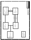
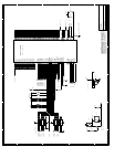
Block diagram
3-1
Boot ROM
3-4
C
CD-ROM drive 2-4
Celeron™ Processor
2-1
Clock synthesizer 3-6
Clocking
3-3
Connectors
J1, keyboard and mouse
4-5
J11, power connector
4-3
J13, AGP connector
4-10
J2, ITP connector 4-4
J2, USB connector
4-4
J3, parallel port
4-5
J4, serial ports 4-6
JP1, floppy connector
4-7
JP4/JP3, IDE connector
4-6
D
DIMM
installing
2-7
Documents online 1-2
DRAM
3-4
Drive assignments
5-4
E
Embedded BIOS 2-3, 5-1
Embedded BIOS Integrated Debugger
5-8
Embedded BIOS Manufacturing Mode 5-9
Evaluation board
2-1
Expansion slots
4-2
F
Floppy connector 4-7
Floppy drive
2-4, 3-5
installing 2-7
G
General Software, Inc. 2-3
H
Hard disk
installing
2-6
I
I/O, legacy support 3-4
IDE connectors (JP3, JP4)
4-6
IDE interface 3-5
Installation
2-5
Instructions, notational conventions
1-1
Intel® Celeron™ Processor 2-1
ISA connectors
3-5
ITP Debugger connector
4-4
ITP debugger port 3-3
J
Jumpers
default settings 4-11
J14, enable spread spectrum clocking
4-11