


Celeron™ Processor Development Kit Manual
3-3
Theory of Operation
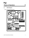
3.2.2.1 System Bus Interface
The 82443BX supports a maximum of 4 Gbytes of memory address space from the processor
perspective. The largest address size is 32 bits. The 82443BX provides bus control signals and
address paths for transfers between the processor bus, PCI bus, Accelerated Graphics Port and
main memory. The 82443BX supports a 4-deep-in-order queue, which provides support for
pipelining of up to four outstanding transaction requests on the system bus.
For system bus-to-PCI transfers, the addresses are either translated or directly forwarded on the
PCI bus, depending on the PCI address space being accessed. When the access is to a PCI
configuration space, the processor I/O cycle is mapped to a PCI configuration space cycle. When
the access is to a PCI I/O or memory space, the processor address is passed without modification to
the PCI bus. Certain memory address ranges are dedicated for a graphics memory address space.
When this space or a portion of it is mapped to main DRAM, the address is translated by the AGP
address remapping mechanism and the request is forwarded to the DRAM subsystem. A portion of
the graphics aperture can be mapped on the AGP, and the corresponding system bus cycles
accessing that range are forwarded to the AGP without any translation. The AGP address map
defines other system bus cycles that are forwarded to the AGP.
3.2.2.2 Accelerated Graphics Port (AGP) Interface
The 82443BX supports an AGP interface. The AGP interface has a maximum theoretical transfer
rate of ~532 Mbytes/s.
3.2.2.3 System Clocking
The 82443BX operates the system bus interface at 66 MHz, the PCI bus at 33 MHz and the AGP at
a transfer rate of 66/133 MHz. The 82443BX clocking scheme uses an external clock synthesizer
that produces reference clocks for the system bus and PCI interfaces. The 82443BX generates the
AGP and DRAM clock signals. Please refer to the CK97 Clock Synthesizer/Driver Specification
(order number 243867).
3.2.3 ITP
The evaluation board is populated with a 2.5 V ITP debugger port. The ITP port provides a path for
debugger tools like emulators, in-target probes, and logic analyzers to gain access to the Celeron
processor registers and signals without affecting high speed operation. This allows the system to
operate at full speed with the debugger attached.